iv
zt1100/xz100 and xt1000 Series
Troubleshooting and Self-Repair Guide
Reference Information
....................................................................................................
57
Password Removal Policy
..............................................................................................................
57
Hewlett-Packard Display Quality Statement
..................................................................................
57
Figures
Figure 1. Front View
...............................................................................................................................
5
Figure 2. Back View
...............................................................................................................................
6
Figure 3. Bottom View
............................................................................................................................
7
Figure 4. Main Status Lights
...................................................................................................................
8
Figure 5. Keyboard Status Lights
............................................................................................................
9
Figure 6. Multimedia Buttons and Status Panel (selected models)
.........................................................
9
Figure 7. Pressing the Reset Switch
......................................................................................................
11
Figure 8. Removing the Battery
............................................................................................................
40
Figure 9. Releasing the Plug-in Module
...............................................................................................
41
Figure 10. Removing the Hard Disk Drive
...........................................................................................
42
Figure 11. Removing the Hard Disk Tray
.............................................................................................
43
Figure 12. Removing the Mini-PCI Card
..............................................................................................
45
Figure 13. Removing the Keyboard Cover Retaining Screws
..............................................................
46
Figure 14. Removing the Keyboard Cover
...........................................................................................
47
Figure 15. Loosening the Keyboard Retaining Screws
.........................................................................
48
Figure 16. Disconnecting the Keyboard
................................................................................................
49
Figure 17. Removing an Expansion SDRAM Module
.........................................................................
50
Figure 18. Installing an Expansion SDRAM Module
...........................................................................
51
Figure 19. Removing the System SDRAM Module
.............................................................................
51
Figure 20. Removing the Speakers
.......................................................................................................
52
Figure 21. Removing the Fan
................................................................................................................
54
Tables
Table 1. Battery Replacement Part Numbers
........................................................................................
40
Table 2. Optical Drive Module Replacement Part Numbers
.................................................................
41
Table 3. Hard Disk Drive Replacement Part Numbers
.........................................................................
42
Table 4. Mini-PCI Card Replacement Part Numbers
............................................................................
44
Table 5. Keyboard Cover Replacement Part Numbers
.........................................................................
46
Table 6. Keyboard Replacement Part Numbers
....................................................................................
48
Table 7. SDRAM Module Replacement Part Numbers
........................................................................
50
Table 8. Speaker Replacement Part Numbers
.......................................................................................
52
Table 9. Fan Replacement Part Numbers
..............................................................................................
53
Table 10. Replacing Small Parts
...........................................................................................................
55
Table 11. Accessories
...........................................................................................................................
55
 1
1 2
2 3
3 4
4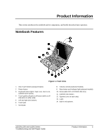 5
5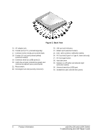 6
6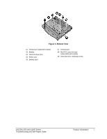 7
7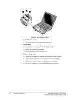 8
8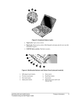 9
9 10
10