HP ProBook 650 Maintenance and Service Guide - Page 56
Optical drive, Service door see
 |
View all HP ProBook 650 manuals
Add to My Manuals
Save this manual to your list of manuals |
Page 56 highlights
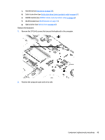
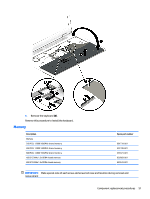
Optical drive Description Optical drive Optical drive/Blu-ray combo for 14" products Optical drive/DVD combo for 14" products Optical drive/DVD ROM combo for 14" products Optical drive/Blu-ray combo for 15" products Optical drive/DVD combo for 15" products Optical drive/DVD ROM combo for 15" products Spare part number 840688-001 840689-001 840690-001 840741-001 840742-001 840743-001 IMPORTANT: Make special note of each screw and screw lock size and location during removal and replacement Before removing the optical drive, follow these steps: 1. Shut down the computer. 2. Disconnect all external devices connected to the computer. 3. Disconnect the power from the computer by first unplugging the power cord from the AC outlet and then unplugging the AC adapter from the computer. 4. Remove the following components: a. Service door (see Service door on page 37). b. Battery (see Battery on page 38). c. Hard drive (see Hard drive on page 39). d. Solid-state drive (see Solid-state drive (select products only) on page 41). e. WWAN module (see WWAN module (select products only) on page 42). f. WLAN module (see WLAN module on page 44). Remove the optical drive: 1. Remove 1 Phillips M2.0x8 screw (1). 46 Chapter 5 Removal and replacement procedures for Customer Self-Repair parts
-
 1
1 -
2
-
3
-
4
-
5
-
6
-
7
-
8
-
9
-
10
-
11
-
12
-
13
-
14
-
15
-
16
-
17
-
18
-
19
-
20
-
21
-
22
-
23
-
24
-
25
-
26
-
27
-
28
-
29
-
30
-
31
-
32
-
33
-
34
-
35
-
36
-
37
-
38
-
39
-
40
-
41
-
42
-
43
-
44
-
45
-
46
-
47
-
48
-
49
-
50
-
 51
51 -
 52
52 -
 53
53 -
 54
54 -
 55
55 -
 56
56 -
 57
57 -
 58
58 -
 59
59 -
 60
60 -
 61
61 -
62
-
63
-
64
-
65
-
66
-
67
-
68
-
69
-
70
-
71
-
72
-
73
-
74
-
75
-
76
-
77
-
78
-
79
-
80
-
81
-
82
-
83
-
84
-
85
-
86
-
87
-
88
-
89
-
90
-
91
-
92
-
93
-
94
-
95
-
96
-
97
-
98
-
99
-
100
-
101
-
102
-
103
-
104
-
105
-
106
-
107
-
108
-
109
-
110
-
111
-
112
-
113
-
114
-
115
-
116
-
117
-
118
-
119
-
120
-
121
-
122
-
123
-
124
-
125
-
126
-
127
-
128
-
129
-
130
-
131
-
132
-
133
-
134
-
135
-
136
-
137
-
138
-
139
-
140
-
141
-
142
-
143
-
144
-
145
-
146
 |
 |
