HP ProBook 650 Maintenance and Service Guide - Page 65
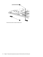
Hinge cover, Remove the 2 M2x5L P1 screws
 |
View all HP ProBook 650 manuals
Add to My Manuals
Save this manual to your list of manuals |
Page 65 highlights
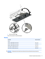
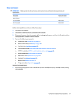
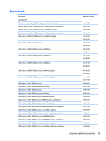
Hinge cover Description Hinge Kit for 14" products Hinge Kit for 15" products Hinge Kit for 14" products with a touch screen Hinge Kit for 15" products with a touch screen Hinge cover for 14" products Hinge cover for 15" products Hinge cover for 14" products with a touch screen Hinge cover for 15" products with a touch screen Spare part number 840684-001 840737-001 845830-001 845835-001 840685-001 840738-001 840686-001 845835-001 IMPORTANT: Make special note of each screw and screw lock size and location during removal and replacement Before removing the hinge covers, follow these steps: 1. Turn off the computer. If you are unsure whether the computer is off or in Hibernation, turn the computer on, and then shut it down through the operating system. 2. Disconnect the power from the computer by unplugging the power cord from the computer. 3. Disconnect all external devices from the computer. 4. Remove the following components: a. Service door (see Service door on page 37). b. Remove the battery (see Battery on page 38) c. Hard drive (see Hard drive on page 39). d. Solid-state drive (see Solid-state drive (select products only) on page 41). e. WWAN module (see WWAN module (select products only) on page 42). f. WLAN module (see WLAN module on page 44). g. Optical drive (see Optical drive on page 46). h. Keyboard (see Keyboard on page 48). i. Memory (see Memory on page 51). Remove the hinge covers: ▲ Remove the 2 M2x5L P1 screws (1), and then remove the hinge covers (2). Component replacement procedures 55
-
 1
1 -
2
-
3
-
4
-
5
-
6
-
7
-
8
-
9
-
10
-
11
-
12
-
13
-
14
-
15
-
16
-
17
-
18
-
19
-
20
-
21
-
22
-
23
-
24
-
25
-
26
-
27
-
28
-
29
-
30
-
31
-
32
-
33
-
34
-
35
-
36
-
37
-
38
-
39
-
40
-
41
-
42
-
43
-
44
-
45
-
46
-
47
-
48
-
49
-
50
-
51
-
52
-
53
-
54
-
55
-
56
-
57
-
58
-
59
-
 60
60 -
 61
61 -
 62
62 -
 63
63 -
 64
64 -
 65
65 -
 66
66 -
 67
67 -
 68
68 -
 69
69 -
 70
70 -
71
-
72
-
73
-
74
-
75
-
76
-
77
-
78
-
79
-
80
-
81
-
82
-
83
-
84
-
85
-
86
-
87
-
88
-
89
-
90
-
91
-
92
-
93
-
94
-
95
-
96
-
97
-
98
-
99
-
100
-
101
-
102
-
103
-
104
-
105
-
106
-
107
-
108
-
109
-
110
-
111
-
112
-
113
-
114
-
115
-
116
-
117
-
118
-
119
-
120
-
121
-
122
-
123
-
124
-
125
-
126
-
127
-
128
-
129
-
130
-
131
-
132
-
133
-
134
-
135
-
136
-
137
-
138
-
139
-
140
-
141
-
142
-
143
-
144
-
145
-
146
 |
 |
