Husqvarna 562 XP G Workshop Manual
Husqvarna 562 XP G Manual
 |
View all Husqvarna 562 XP G manuals
Add to My Manuals
Save this manual to your list of manuals |
Husqvarna 562 XP G manual content summary:
- Husqvarna 562 XP G | Workshop Manual - Page 1
Workshop Manual 555 560XP/XPG 562XP/XPG English - Husqvarna 562 XP G | Workshop Manual - Page 2
- Husqvarna 562 XP G | Workshop Manual - Page 3
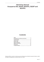
Contents Workshop Manual Husqvarna 555, 560XP, 560XPG, 562XP and 562XPG Contents Index 4 Introduction and safety instructions 6 Technical data 10 Service tools 12 Service data 14 Safety equipment 16 Repair instructions 24 Carburettor 34 Troubleshooting 56 Husqvarna AB has a policy of - Husqvarna 562 XP G | Workshop Manual - Page 4
instructions 7 General 7 General Instructions 8 Modifications 7 Numbering 7 Safety 7 Special Instructions the cylinder 48 S Service data 14 Service tools 12 Starter 25, Symbols Symbols in the Workshop Manual 9 Symbols on the saw 9 T Tank unit Troubleshooting 57 Troubleshooting methods 58 4 - English - Husqvarna 562 XP G | Workshop Manual - Page 5
V Vibration damping system 43 Assembly 43 Cleaning and inspection 43 Dismantling 43 Index English - 5 - Husqvarna 562 XP G | Workshop Manual - Page 6
safety regulations Contents 2.1 General ...7 2.2 Safety ...7 2.3 Target group ...7 2.4 Modifications...7 2.5 Tools ...7 2.6 Structure ...7 2.7 Numbering ...7 2.8 General instructions ...8 2.9 Special instructions ...8 2.10 Symbols on the saw ...9 2.11 Symbols in the Workshop Manual 9 6 - English - Husqvarna 562 XP G | Workshop Manual - Page 7
the chain saw in question. 2.5 Tools Special tools are required for some stages. All service tools are listed in the Workshop Manual. Usage is made apparent in each section. Always use Husqvarna's original: • Spare parts • Service tools • Accessories 2.6 Structure This Workshop Manual can be - Husqvarna 562 XP G | Workshop Manual - Page 8
safety instructions 2.8 General Instructions The workshop where the chain saw is to be repaired must be equipped with safety equipment in accordance with local regulations. No one may repair the chain saw unless they have read and understood the content of this Workshop Manual. This workshop manual - Husqvarna 562 XP G | Workshop Manual - Page 9
below are embedded on the chain saw. Choke Lever Introduction and safety instructions 2.11 Symbols in the Workshop Manual This symbol warns of personal injury when the instructions are not followed. Refuelling Stop button Chain oil fill. Chain brake Decompression valve Fuel pump Adjusting - Husqvarna 562 XP G | Workshop Manual - Page 10
9600 3.5 / 4.8 / 9600 3.5 / 4.8 / 9600 Electrode gap Ignition system mm/inch 555: 0,5 / 0.02 560XP/XPG: 0,5 / 0.02 562XP/XPG: 0,5 / 0.02 SEM cm/inch max. output - speed m/s - rpm Chain pitch mm/inch Drive link mm/inch 555: 33-61 / 13-24 560XP/XPG: 33-61 / 13-24 562XP/XPG: 38- - Husqvarna 562 XP G | Workshop Manual - Page 11
/XPG: 3800 3800 3800 Spark plug NGK CMR6H NGK CMR6H NGK CMR6H Automatic oil pump Yes Yes Yes GAS Volume fuel tank Litre/US. pint 555: 560XP/XPG: 562XP/XPG: 0,65 / 1.37 0,65 / 1,37 0,65 / 1.37 Capacity oil pump at 9,000 rpm, ml/min 6-15 6-15 8-18 OIL Volume oil tank - Husqvarna 562 XP G | Workshop Manual - Page 12
Service tools 1 4 Service tools 2 3 4 5 6 4 mm 4 mm 5 mm 7 8 9 10 12 - English 11 12a 12b - Husqvarna 562 XP G | Workshop Manual - Page 13
15 17 Service tools Pos 7 Assembly fixture 8 Pressure gauge Securing the chain saw Pressure testing 502 51 02-01 531 03 06 tool Assembling the sealring 12b Guide sleeve Assembling the sealring 13a crankshaft 17 Engine Diagnostic Tool Diagnosis and troubleshooting 501 97 64-01 502 50 06- - Husqvarna 562 XP G | Workshop Manual - Page 14
12-15 Nm 5mm 5 Service data 18-20Nm 16mm 12-14Nm 13mm 8-10Nm 4mm 1,5-2Nm 4mm 1-2Nm 12-15 Nm 5mm Min. 15Nm 13mm 1-2Nm 4-5Nm 4mm 5-6Nm 4mm Min. - Husqvarna 562 XP G | Workshop Manual - Page 15
9-11Nm 4mm 1-2Nm 7-9Nm 4mm 3-4Nm 4mm 22-25Nm 13mm Service data 3-4Nm 4mm 6-8Nm 4mm 4-5Nm 4mm 9-11Nm 4mm 6-8Nm 4mm 3-4Nm 4mm 2-3Nm 4mm 3,5-4,5Nm 4mm 3-4Nm 4mm 7-9Nm 4mm 8-10Nm 4mm 3,5-4,5Nm 4mm English - 15 - Husqvarna 562 XP G | Workshop Manual - Page 16
Safety equipment 6 Safety equipment Contents 6.1 Dismantling the chain brake 17 6.2 Assembling the chain brake 18 6.3 Dismantling the muffler 19 6.4 Assembling the muffler ...19 6.5 Replacing the chain catcher 20 6.6 Dismantling the start/stop control 20 6.7 Assembling the start/stop control - Husqvarna 562 XP G | Workshop Manual - Page 17
. Carefully tighten the clutch housing in a vice. Release the brake by using the saw's hand guard as a tool. Mesh with the brake and tighten anti-clockwise until all components. Parts Fig 4 must be replaced if cracked or show signs of other defects. Always use original spare parts. • Measure the - Husqvarna 562 XP G | Workshop Manual - Page 18
using 1-1.5 Nm tightening torque. See figure 8. Fig 8 4 Tighten the brake by using the saw's hand guard as a tool. Mesh with the brake and tighten clockwise until the brake is the plastic housing into its groove. Tighten the chain guide plate in place. Fit the: • bar • chain • clutch shoe • cylinder cover Fig - Husqvarna 562 XP G | Workshop Manual - Page 19
instruction below. Functional inspection: Do not turn on the motor when carrying out this inspection. Bar length Height 38 cm/15" 50 cm/20" • Hold the chain saw components carefully. Parts must be replaced if cracked or show signs of other defects. Always use original spare parts. The spark - Husqvarna 562 XP G | Workshop Manual - Page 20
chapter. 2 Loosen screw B and dismantle the stop control A. See figure 14. Unhook the rubber collar around the control from the guide plugs. Cleaning and inspection Clean and check carefully all components. Parts must be replaced if cracked or show signs of other defects. Always use original spare - Husqvarna 562 XP G | Workshop Manual - Page 21
control (A) and tighten screw (B) in place at a torque of 1 Nm. Slide in the stop control in the rubber sleeve C and hook the sleeve on the guide taps. See figure 15. Safety equipment Fig 15 2 Attach the cables as outlined in figure 16. 3 Attach the air filter holder. See the "Assembling the - Husqvarna 562 XP G | Workshop Manual - Page 22
the spring. See figure 22. Fig 21 5 Cleaning and inspection • Carefully clean and check all parts. See figure 13. Parts must be replaced if cracked or show signs of other defects. Always use original spare parts. • Check that the spring is intact and retains all its tension. Fig 22 22 - English - Husqvarna 562 XP G | Workshop Manual - Page 23
6.10 Assembling the throttle control lock, throttle control and spring 1 Lubricate the pin and joined surfaces with a light oil. Hook on the throttle cable (D). Slide in the throttle control and make sure the spring is fitted as outlined in figure 24. NOTE! Make sure that the rear end of the - Husqvarna 562 XP G | Workshop Manual - Page 24
Repair Instructions 7 Repair instructions Contents 7.1 Dismantling the starter ...25 7.2 Replacing a broken or worn starter cord 26 7.3 Tensioning the return spring 26 7.4 Replacing a broken return spring 27 7.5 Starter assembly...27 7.6 - Husqvarna 562 XP G | Workshop Manual - Page 25
hold the starter against the crankcase and remove the starter. Repair Instructions 2 Pull the cord out about 30 cm and lift it into on the cassette and remove the cassette and spring. Cleaning and inspection Clean the parts and check: • The starter cord. • That the starter pawls on the flywheel - Husqvarna 562 XP G | Workshop Manual - Page 26
Repair instructions 7.2 Replacing a broken or worn starter cord When the starter cord torque of 2-3 Nm. Cleaning and inspection: • Clean and check carefully all components. Worn or damaged parts must be replaced. Lubricate the return spring with a light oil. Fig 3b 7.3 Tensioning the return spring - Husqvarna 562 XP G | Workshop Manual - Page 27
". See also the "Dismantling the starter" chapter. 7.5 Starter assembly 1 Position the starter against the crankcase and tighten the screws at a tightening torque of 3-4 Nm. Repair Instructions English - 27 - Husqvarna 562 XP G | Workshop Manual - Page 28
Instructions 7.6 Dismantling the ignition module and flywheel 1 Remove the cylinder cover. Remove the starter. Snap off the ignition cable from the guide rail and remove the guide in the crankcase. Cleaning and inspection • Clean all parts, especially the tapers on the flywheel and shafts. • - Husqvarna 562 XP G | Workshop Manual - Page 29
as outlined in "Assembling the carburettor". 6 Press the ignition lead into the holder on the partition wall. 7 Then fit: • The air nozzle • The guide rail and press the cable in place • the spark plug hat by unscrewing the piston stop. • The starter, at a tightening torque of 2.5-3.5 Nm • The - Husqvarna 562 XP G | Workshop Manual - Page 30
Repair Instructions 7.8 Dismantling the centrifugal clutch 1 Remove the cylinder cover. Release Cleaning and inspection • Clean and check all parts carefully. Parts must be replaced if cracked or showing signs of other defects. Always use original spare parts. • Check the thickness of the clutch - Husqvarna 562 XP G | Workshop Manual - Page 31
wheel. See figure 18. 3 Unscrew the chain guide plate. See figure 19. 4 Loosen the screws on parts carefully. Parts must be replaced if cracked or showing signs of other defects. Always use original spare parts. • Lubricate all moving parts with chain oil. Fig 18 Fig 19 Fig 20 Repair Instructions - Husqvarna 562 XP G | Workshop Manual - Page 32
Repair Instructions 7.11 Assembling the oil pump and screen 1 Lower the oil filter in place and replace the oil pump as outlined in figure 19 and tighten - Husqvarna 562 XP G | Workshop Manual - Page 33
26. Cleaning and inspection Clean and check all parts carefully. Parts must be replaced if cracked or showing signs of other defects. Always use original spare parts. 7.13 Assembling the intake system 1 Assemble the in "Assembling the carburettor". Fig 25b Fig 26 Repair Instructions English - 33 - Husqvarna 562 XP G | Workshop Manual - Page 34
Repair Instructions 7.14 Carburettor WARNING! The fuel used in the chain saw has the following hazardous properties: 1. The figures accompanying this description do not correspond with the carburettor on the chain saw. They show only the principle of design and function. Design The carburettor - Husqvarna 562 XP G | Workshop Manual - Page 35
throttle mode, the throttle valve I is partly open and the choke valve H is fully open. Fuel is supplied through the diffuser jets D and E. The throttle valve, J, starts to open. See figure 32. Fig 31 Repair Instructions In the full throttle mode both valves are open and fuel is supplied through - Husqvarna 562 XP G | Workshop Manual - Page 36
Repair Instructions Dismantling the carburettor 1 Dismantle the cylinder cover and the air filter. 2 Loosen the screws, F. Unhook the rubber attachment G on both sides. See Figure 35. 3 Loosen - Husqvarna 562 XP G | Workshop Manual - Page 37
valve S, and remove the shafts with lever arms and springs (see figure 39). 11 If necessary, dismantle the AutoTune AB unit. See figure 39. L M P Repair Instructions H J K Q R Fig 38 English - 37 - Husqvarna 562 XP G | Workshop Manual - Page 38
See figure 39. 6. Use the service tool, Engine Diagnostic Tool 576 69 23-01, to inspect the AutoTune unit. See separate instruction. Assembly Observe cleanliness when assembling the can be used. Refer to the local support page for more information. S V T AB W X Y U Fig 39 Z 38 - English - Husqvarna 562 XP G | Workshop Manual - Page 39
4. Assemble needle valve M with lever arm Q, shaft L and spring R, and tighten screw P. (Fit the expansion washer). See figure 40. Repair Instructions Fig 40 5. Check using a ruler or the like that the lever is level with the assembly plane on the cover. If necessary, the lever arm - Husqvarna 562 XP G | Workshop Manual - Page 40
Instructions Pressure testing the carburettor Pressure testing should be carried out with the carburettor fully assembled. Testing should always be carried out after the carburettor has been repaired, but a test can also be made for troubleshooting membrane Fitting on the saw 1 Press the connector together - Husqvarna 562 XP G | Workshop Manual - Page 41
47. • NOTE! Make sure that the fuel and return hoses are not crushed. Fig 46 3 Position the guide taps on the air filter holder in the rubber grommets, G. See figure 48. Fig 47 Repair Instructions D E 4 Hook on the throttle cable, E. See figure 46. Fasten the return hose B and secure it in its - Husqvarna 562 XP G | Workshop Manual - Page 42
Repair Instructions 7.15 Tank unit WARNING! The fuel used in the chain saw has the following hazardous properties: 1. The fluid and its vapour are poisonous. 2. Can cause skin irritation. 3. Is highly inflammable. Dismantling 1. Drain the fuel from the - Husqvarna 562 XP G | Workshop Manual - Page 43
the springs on the handle bar using a 4 mm Allen key (tool 502 50 18-01). 2. Assemble the following parts: •Tank unit and handle. See "Assembling the tank unit". •Cylinder cover. See the Operator's Manual. •Bar and chain. See the Operator's Manual. Fig 56 Fig 57 Repair Instructions English - 43 - Husqvarna 562 XP G | Workshop Manual - Page 44
Repair Instructions 7.18 Replacing the fuel filter NOTE! Fluted pliers may not be used with the fuel hose. They can cause material damage resulting in damage to - Husqvarna 562 XP G | Workshop Manual - Page 45
following areas: • The piston crown • The top of the cylinder bore (inside) • The cylinder exhaust port • The base of the cylinder and/or crankcase Repair Instructions English - 45 - Husqvarna 562 XP G | Workshop Manual - Page 46
Repair Instructions Check the following: • That the cylinder's surface coating is not worn. Especially the upper part of the cylinder. • That the cylinder does not have any chafe or cutting marks. • That the piston is free of score marks. Minor scratches can - Husqvarna 562 XP G | Workshop Manual - Page 47
much or incorrect oil in the fuel. See Figure 63. Piston ring breakage 1. Piston ring worn out. 2. Oversized piston ring groove. A Fig 63 Repair Instructions B 7.22 Assembling the piston and cylinder 1 Oil the gudgeon pin bearing with two-stroke oil and insert it into the crank rod. See figure 64 - Husqvarna 562 XP G | Workshop Manual - Page 48
Repair Instructions 7.23 Pressure testing the cylinder 1 Loosen • The cylinder cover • The carburettor 2 Attach the cover plate 574 71 14-01 and plug 574 70 12-01. - Husqvarna 562 XP G | Workshop Manual - Page 49
* • The ignition module • Cabling • The oil pump * See specific instruction. Fig 69 NOTE! Take care to prevent any dirt and foreign particles from side's crankcase half. 6. Carefully pull the crankcase halves apart. Two guide pins keep the crankcase halves together. Lift out the connecting rod - Husqvarna 562 XP G | Workshop Manual - Page 50
Repair Instructions 7. If required, remove the crankshaft bearing from the crankcase. Proceed crankcase, take care to prevent any dirt and foreign particles from entering. Fig 73 Clean all parts and scrape off all gasket remains from the contact surfaces on the crankcase halves. Check the following - Husqvarna 562 XP G | Workshop Manual - Page 51
half. See Figure 76. Tighten until the crankshaft collar comes into contact with the bearing. 4. Insert the guide pin in the crankcase half on the clutch side, apply grease and fit the gasket(C). See Figure 77. the crankcase. Fig 76 Fig 77 Fig 78 Fig 79 Repair Instructions x4 English - 51 - Husqvarna 562 XP G | Workshop Manual - Page 52
Repair Instructions 8 Assemble the following parts: A. Tank unit. See page 43. B. Piston and cylinder. See page the following parts: On the flywheel side: • Starter. See page 25. • Flywheel. See page 28. On the clutch side: • Bar and chain. See the Operator's Manual. • Chain guide plate. See - Husqvarna 562 XP G | Workshop Manual - Page 53
7.25 Assembling a complete crankshaft 1 Fit the complete crankshaft in the crankcase. Fit the following parts: • The piston and cylinder * • The fuel unit * • The handle system * • The clutch * • The chain and bar. • The clutch cover * See specific instruction. Repair Instructions English - 53 - Husqvarna 562 XP G | Workshop Manual - Page 54
Repair Instructions 7.26 Replacing the bar bolt Replacing a bar bolt with intact crankcase 1 Empty the oil tank. 2 Knock in the old bar bolts from the outside so that they end up in the oil tank. 3 Remove the bolts from the oil tank. 4 Attach a wire to the head of the bar bolt, lower the - Husqvarna 562 XP G | Workshop Manual - Page 55
English - 55 - Husqvarna 562 XP G | Workshop Manual - Page 56
Troubleshooting 8 Troubleshooting Contents 8.1 Troubleshooting ...57 8.2 Troubleshooting methods 58 56 - English - Husqvarna 562 XP G | Workshop Manual - Page 57
on the chain saw are divided into four groups. Within each group possible operating faults are listed to the left while the probable fault alternatives are listed to the right. The most likely fault is listed first, etc. See separate instruction for Autotune troubleshooting. Starting Idling (low - Husqvarna 562 XP G | Workshop Manual - Page 58
Blocked air filter Faulty pump diaphragm Faulty diffuser jet 8.2 Troubleshooting methods In addition to faults given in the above schematic, troubleshooting can be carried out on a specific component or specific chain saw system. The different procedures are described in respective sections and - Husqvarna 562 XP G | Workshop Manual - Page 59
• 115 26 56-26 2011W31
-
 1
1 -
 2
2 -
 3
3 -
 4
4 -
 5
5 -
 6
6 -
 7
7 -
8
-
9
-
10
-
11
-
12
-
13
-
14
-
15
-
16
-
17
-
18
-
19
-
20
-
21
-
22
-
23
-
24
-
25
-
26
-
27
-
28
-
29
-
30
-
31
-
32
-
33
-
34
-
35
-
36
-
37
-
38
-
39
-
40
-
41
-
42
-
43
-
44
-
45
-
46
-
47
-
48
-
49
-
50
-
51
-
52
-
53
-
54
-
55
-
56
-
57
-
58
-
59
 |
 |

Workshop Manual
English
555 560XP/XPG
562XP/XPG