IBM 8840 Installation Guide - Page 32
Installing, additional, microprocessor
 |
UPC - 000435863799
View all IBM 8840 manuals
Add to My Manuals
Save this manual to your list of manuals |
Page 32 highlights
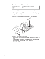
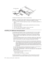
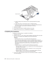
Drive-tray assembly Drive handle Filler panel Complete the following steps to install a hard disk drive. Attention: To maintain proper system cooling, do not operate the server for more than 10 minutes without either a drive or a filler panel installed in each bay. 1. Read the safety information beginning on page v and "Installation guidelines" on page 7. 2. Remove the filler panel. 3. Place the drive handle in the open position and slide the drive into the bay. 4. Close the drive handle. 5. If you have other options to install or remove, do so now. 6. Go to "Completing the installation" on page 22. Installing an additional microprocessor The following notes describe the type of microprocessor that the server supports and other information that you must consider when installing a microprocessor: v When you install the microprocessor in socket J23, you must also install the voltage regulator module (VRM) that comes with the microprocessor in VRM connector J72. v If the thermal-grease protective cover (for example, a plastic cap or tape liner) is removed from the heat sink or fan sink, do not touch the thermal grease on the bottom of the heat sink or fan sink or set down the heat sink or fan sink. Note: Removing the heat sink or fan sink from the microprocessor destroys the even distribution of the thermal grease and requires replacing the thermal grease. Setting down the heat sink or fan sink onto any surface when the thermal-grease protective cover is removed will contaminate the thermal grease. If the thermal grease becomes contaminated with particles, it must be replaced. For information about replacing contaminated thermal grease on the heat sink or fan sink, contact IBM Services. For support phone numbers, go to http://www.ibm.com/planetwide/, or in the U.S. and Canada, call 1-800-IBM-SERV (1-800-426-7378). Have the following information ready when you call: - Machine type and model - Serial number of your server or computer The following illustration is a simplified layout of the microprocessor connector locations and other microprocessor-related components on the system board. 18 IBM xSeries 346 Type 8840: Installation Guide
-
 1
1 -
2
-
3
-
4
-
5
-
6
-
7
-
8
-
9
-
10
-
11
-
12
-
13
-
14
-
15
-
16
-
17
-
18
-
19
-
20
-
21
-
22
-
23
-
24
-
25
-
26
-
 27
27 -
 28
28 -
 29
29 -
 30
30 -
 31
31 -
 32
32 -
 33
33 -
 34
34 -
 35
35 -
 36
36 -
 37
37 -
38
-
39
-
40
-
41
-
42
-
43
-
44
-
45
-
46
-
47
-
48
-
49
-
50
-
51
-
52
-
53
-
54
-
55
-
56
-
57
-
58
-
59
-
60
-
61
-
62
-
63
-
64
-
65
-
66
-
67
-
68
-
69
-
70
-
71
-
72
-
73
-
74
-
75
-
76
-
77
-
78
-
79
-
80
-
81
-
82
-
83
-
84
-
85
-
86
-
87
-
88
-
89
-
90
-
91
-
92
-
93
-
94
-
95
-
96
-
97
-
98
-
99
-
100
-
101
-
102
-
103
-
104
-
105
-
106
-
107
-
108
 |
 |
