IBM 8840 Installation Guide - Page 39
Server, power, controls, indicators
 |
UPC - 000435863799
View all IBM 8840 manuals
Add to My Manuals
Save this manual to your list of manuals |
Page 39 highlights
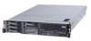
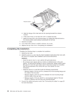
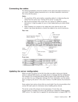
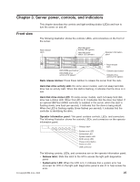
Chapter 3. Server power, controls, and indicators Front view This chapter describes the controls and light-emitting diodes (LEDs) and how to turn the server on and off. The following illustration shows the controls, LEDs, and connectors on the front of the server. Rack release latch Hard disk drive activity LED (green) Hard disk drive status LED (amber) Operator information panel Rack release latch DVD-ROM eject button DVD-ROM drive activity LED (green) Diskette-eject button Diskette drive activity LED (green) Rack release latches: Press these latches to release the server from the rack. Hard disk drive activity LED: On some server models, each hot-swap hard disk drive has an activity LED. When this LED is flashing, it indicates that the drive is in use. Hard disk drive status LED: On some server models, each hot-swap hard disk drive has a status LED. When this LED is lit, it indicates that the drive has failed. If an optional IBM ServeRAID controller is installed in the server, when this LED is flashing slowly (one flash per second), it indicates that the drive is being rebuilt. When the LED is flashing rapidly (three flashes per second), it indicates that the controller is identifying the drive. Operator information panel: This panel contains controls, LEDs, and connectors. The following illustration shows the controls, LEDs, and connectors on the operator information panel. Release latch System-error LED Information LED System-locator LED SCSI activity LED Power-control button Power-on LED USB connector The following controls, LEDs, and connectors are on the operator information panel: v Release latch: Slide this latch to the left to access the light path diagnostics panel. v System-error LED: When this LED is lit, it indicates that a system error has occurred. An LED on the light path diagnostics panel is also lit to help isolate the error. © Copyright IBM Corp. 2006 25
-
 1
1 -
2
-
3
-
4
-
5
-
6
-
7
-
8
-
9
-
10
-
11
-
12
-
13
-
14
-
15
-
16
-
17
-
18
-
19
-
20
-
21
-
22
-
23
-
24
-
25
-
26
-
27
-
28
-
29
-
30
-
31
-
32
-
33
-
 34
34 -
 35
35 -
 36
36 -
 37
37 -
 38
38 -
 39
39 -
 40
40 -
 41
41 -
 42
42 -
 43
43 -
 44
44 -
45
-
46
-
47
-
48
-
49
-
50
-
51
-
52
-
53
-
54
-
55
-
56
-
57
-
58
-
59
-
60
-
61
-
62
-
63
-
64
-
65
-
66
-
67
-
68
-
69
-
70
-
71
-
72
-
73
-
74
-
75
-
76
-
77
-
78
-
79
-
80
-
81
-
82
-
83
-
84
-
85
-
86
-
87
-
88
-
89
-
90
-
91
-
92
-
93
-
94
-
95
-
96
-
97
-
98
-
99
-
100
-
101
-
102
-
103
-
104
-
105
-
106
-
107
-
108
 |
 |