Intel S5500WB12V Product Specification
Intel S5500WB12V Manual
 |
View all Intel S5500WB12V manuals
Add to My Manuals
Save this manual to your list of manuals |
Intel S5500WB12V manual content summary:
- Intel S5500WB12V | Product Specification - Page 1
Intel® Server Board S5500WB Technical Product Specification Intel order number E53971-008 Revision 1.9 February, 2012 Enterprise Platforms and Services Division - Intel S5500WB12V | Product Specification - Page 2
Intel® Server Board memory to 128GB. Added support for 5600 series processors. Updated12V SKU board picture (Figure 1). Removed Rapid Boot Toolkit section. Updated NIC LEDs. Updated video resolution. Updated typo in board feature set. Updated typo in board feature set. ii Revision 1.9 Intel - Intel S5500WB12V | Product Specification - Page 3
document may be reproduced, stored in a retrieval system, or transmitted in any form or by any means without the express written consent of Intel Corporation. Intel and Xeon are trademarks or registered trademarks of Intel Corporation. *Other brands and names may be claimed as the property of others - Intel S5500WB12V | Product Specification - Page 4
2.2 Server Board Connector and Component Layout 6 2.2.1 Board Rear Connector Placement 8 2.2.2 Server Board Mechanical Drawings 8 3. Functional Architecture 13 3.1 High Level Product Features 13 3.2 Functional Block Diagram 14 3.3 Processor Subsystem 15 3.3.1 Processor Support 15 - Intel S5500WB12V | Product Specification - Page 5
Intel® Server Board S5500WB TPS Table of Contents 3.7.2 USB 2.0 Support 29 3.8 Network Interface Controller (NIC 30 3.8.1 MAC Address Definition 31 3.8.2 LAN Connector Ordering 31 3.9 Integrated Baseboard Management Controller 31 3.9.1 Integrated BMC Embedded LAN Channel 33 3.9.2 - Intel S5500WB12V | Product Specification - Page 6
Table of Contents Intel® Server Board S5500WB TPS 5.5.2 PCI Express* Power management 43 5.5.3 PMBus* ...43 5.6 out 52 7.1 Power Connectors 52 7.2 7.2.1 System Management Headers 54 Intel® Remote Management Module 3 (Intel® RMM3) Connector 54 7.2.2 BMC Power Cycle Header (12V Only 54 - Intel S5500WB12V | Product Specification - Page 7
Memory Temperature Sensor 79 9.2.3 Board Temperature Sensor 79 9.2.4 Thermals Sensor Placement 79 9.3 Heatsinks ...80 9.3.1 Unified Retention System Support 81 9.4 Errors ...82 9.4.1 PROCHOT# ...82 9.4.2 THERMTRIP# ...82 9.4.3 CATERR# ...82 10. Power Subsystem...83 10.1 Server Board - Intel S5500WB12V | Product Specification - Page 8
Table of Contents Intel® Server Board S5500WB TPS 11.3.1 FCC Verification Statement (USA 86 11.3.2 ICES-003 (Canada 87 11.3.3 Europe (CE POST Code LED Decoder 89 Appendix B: Video POST Code Errors 96 Glossary ...100 Reference Documents ...103 viii Revision 1.9 Intel order number E53971-008 - Intel S5500WB12V | Product Specification - Page 9
11 Figure 8. Secondary Side Height Restrictions 12 Figure 9. Intel® Server Board S5500WB Functional Block Diagram 14 Figure 10. Lifting the load lever of ILM cover 17 Figure 11. Removing the socket cover 17 Figure 12. Installing processor 18 Figure 13. Package Installation/Remove Feature 19 - Intel S5500WB12V | Product Specification - Page 10
List of Figures Intel® Server Board S5500WB TPS Figure 32. Power Distribution Diagram 83 Figure 33. Diagnostic LED Placement Diagram 89 x Revision 1.9 Intel order number E53971-008 - Intel S5500WB12V | Product Specification - Page 11
® Server Board S5500WB System Interconnects 7 Table 3. Intel® Server Board S5500WB Features 13 Table 4. Mixed Processor Configurations 16 Table 5. DIMM Nomenclature 22 Table 6. IOH24D PCI Express* Bus Segments 27 Table 7. NIC 1 Status LED...30 Table 8. RMM3 Features ...34 Table 9. Supported - Intel S5500WB12V | Product Specification - Page 12
List of Tables Intel® Server Board S5500WB TPS Table 32. SGPIO Header (J1B1 55 Table 33 J2K3, J3K1, J7K1, J8K4, J8K5 67 Table 50. 8-pin Fan Connector (J2K1 & J8K3) (MOLEX CONNECTOR CORPORATION 53398- 0890 or 53398-0871 ) ...67 Table 51. System Status LED 71 Table 52. Standard Front Panel - Intel S5500WB12V | Product Specification - Page 13
Intel® Server Board S5500WB TPS List of Tables Revision 1.9 xiii Intel order number E53971-008 - Intel S5500WB12V | Product Specification - Page 14
- Intel S5500WB12V | Product Specification - Page 15
Intel® Server Board S5500WB TPS Introduction 1. Introduction The Intel® Server Board S5500WB is a dual socket server using the Intel® Xeon® Processor 5500 series and 5600 series processors Reference Documents 1.2 Server Board Use Disclaimer Intel Corporation server boards contain a number of - Intel S5500WB12V | Product Specification - Page 16
table provides a high-level product feature list. Feature Processors Memory Chipset I/O Control Power Connections Table 1. Intel® Server Board S5500WB Feature Set Description Support for one or two Intel® Xeon® Processor 5500 and 5600 series processors in FC-LGA 1366 Socket B package with up to - Intel S5500WB12V | Product Specification - Page 17
Intel® Server Board S5500WB TPS Server Board Overview Feature System Fan Support Add-in Adapter Support Video Hard Drive LAN Server Management Description Two 8-pin fan headers for double rotor memory fans and six 4-pin fan headers supporting two processor zones and two memory zones in a - Intel S5500WB12V | Product Specification - Page 18
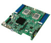
Server Board Overview Intel® Server Board S5500WB TPS 2.1 Intel® Server Board S5500WB Server Board The Intel® Server Board S5500WB has two board SKUs, such as SSI-compliant and 12-V-onlySKU. The board layouts of the SKUs are shown. Figure 1. Intel® Server Board S5500WB 12V 4 Revision 1.9 Intel - Intel S5500WB12V | Product Specification - Page 19
Intel® Server Board S5500WB TPS Server Board Overview Figure 2. Intel Server Board S5500WB SSI Revision 1.9 5 Intel order number E53971-008 - Intel S5500WB12V | Product Specification - Page 20
Server Board Overview Intel® Server Board S5500WB TPS 2.2 Server Board Connector and Component Layout Figure 3. Intel® Server Board S5500WB Components (both SKUs are shown) 6 Revision 1.9 Intel order number E53971-008 - Intel S5500WB12V | Product Specification - Page 21
Intel® Server Board S5500WB TPS Server Board Overview Table 2. Intel® Server Board S5500WB System Interconnects Description A Dual Intel (CPU1) U HDD Power Connector (12V only) Description V Processor Socket 1 W 8 Pin CPU Connector X Processor Socket 2 Y 4-pin Fan Connector (CPU2) Z 4-pin Fan - Intel S5500WB12V | Product Specification - Page 22
Server Board Overview Intel® Server Board S5500WB TPS 2.2.1 Board Rear Connector Placement The Intel® Server Board S5500WB has the following board rear connector placement: Figure 4. Rear Panel Connector Placement: A ID LED Description B Status LED C RJ-45 GbE/Dual USB connector D Dual - Intel S5500WB12V | Product Specification - Page 23
Intel® Server Board S5500WB TPS Server Board Overview Figure 5. Baseboard and Mounting holes Revision 1.9 9 Intel order number E53971-008 - Intel S5500WB12V | Product Specification - Page 24
Server Board Overview Intel® Server Board S5500WB TPS Figure 6. Connector Locations 10 Revision 1.9 Intel order number E53971-008 - Intel S5500WB12V | Product Specification - Page 25
Intel® Server Board S5500WB TPS Server Board Overview Figure 7. Primary Side Height Restrictions Revision 1.9 11 Intel order number E53971-008 - Intel S5500WB12V | Product Specification - Page 26
Server Board Overview Intel® Server Board S5500WB TPS Figure 8. Secondary Side Height Restrictions 12 Revision 1.9 Intel order number E53971-008 - Intel S5500WB12V | Product Specification - Page 27
Intel® Server Board S5500WB Features Board S5500WB 12V S5500WB SSI Form Factor CPU Socket Chipset Memory Slots Ethernet EATX 12‖ x 13‖ B Intel® 5500 Chipset IOH Intel w/ x8 connector Dual GbE, Intel® 82576 Gigabit Ethernet Storage SAS I/O Module SW RAID Processor Support Six SATA II ports (3Gb - Intel S5500WB12V | Product Specification - Page 28
Functional Architecture 3.2 Functional Block Diagram Intel® Server Board S5500WB TPS Figure 9. Intel® Server Board S5500WB Functional Block Diagram 14 Revision 1.9 Intel order number E53971-008 - Intel S5500WB12V | Product Specification - Page 29
memory controller. The Intel® 5600 series processor is the next generation of multi-core processors based on the 32 nm process technology. Processor features vary by SKU and include up to 6 cores and up to 12 MB of shared cache. 3.3.1 Processor Support The Intel® Server Board S5500WB supports - Intel S5500WB12V | Product Specification - Page 30
Functional Architecture Intel® Server Board S5500WB TPS Table 4. Mixed Processor Configurations Error Processor family not identical Severity Fatal Processor cache not identical Fatal Processor frequency (speed) Major not identical System Action The BIOS detects the error condition and - Intel S5500WB12V | Product Specification - Page 31
Intel® Server Board S5500WB TPS Functional Architecture 3.3.3 Installing or Replacing the Processor 3.3.3.1 Installing the Processor To install a processor, follow these instructions: 1. Turn off all peripheral devices connected to the server. 2. Turn off the server. 3. Disconnect the AC power - Intel S5500WB12V | Product Specification - Page 32
Functional Architecture Intel® Server Board S5500WB TPS Figure 12. Installing processor 9. Lower the load plate and load lever of the ILM cover completely. Note: Make has alignment walls at the four corners to provide final alignment of the package. 18 Revision 1.9 Intel order number E53971-008 - Intel S5500WB12V | Product Specification - Page 33
Intel® Server Board S5500WB TPS Functional Architecture Figure 13. Package Installation/Remove Feature 3.3.3.2 Installing the Processor Heatsink(s) CAUTION: The heatsink has Thermal Interface Material (TIM) located on the bottom of it. Use caution when you unpack the heatsink so you do - Intel S5500WB12V | Product Specification - Page 34
Functional Architecture Intel® Server Board S5500WB TPS Figure 14. Installing/Removing Heatsink 3.3.3.3 Removing the Processor Heatsink To remove peer-to-peer communication support), AGP (Accelerated Graphics Port), and so forth, through the appropriate bridges. Each Intel® QPI link consists - Intel S5500WB12V | Product Specification - Page 35
both Registered DIMMs (RDIMMs) and Unbuffered DIMMs (UDIMMs). Mixing of RDIMMs and UDIMMs is not supported. 3.4.1 Supported Memory The Intel® Server Board S5500WB supports six DDR3 memory channels (three per processor socket) with two DIMMs on the first channel and one DIMM on the second and third - Intel S5500WB12V | Product Specification - Page 36
Intel® Server Board S5500WB TPS The memory channels from socket 1 are identified as Channels A, B, and C. The memory channels from socket 2 are identified as Channels D, E, and F. The DIMM identifiers on the silkscreen on the board provide information about the channel, and, therefore the processor - Intel S5500WB12V | Product Specification - Page 37
Server Board S5500WB TPS Functional Architecture The BIOS will always enable high-memory reclaim if it discovers installed physical memory equal to or greater than 4 GB. For the operating system, the reclaimed memory is recoverable only when it supports and enables the PAE feature in the processor - Intel S5500WB12V | Product Specification - Page 38
Functional Architecture Intel® Server Board S5500WB TPS Figure 17. Installing Memory 4. Make sure the clips at either end of the DIMM socket(s) are pushed outward to the open position (see letter ―A‖ in the figure above). 5. Holding - Intel S5500WB12V | Product Specification - Page 39
redundancy. On the Intel® 5500 series based Intel server boards, mirroring is achieved across channels. Active channels hold the primary image and the other channels hold the secondary image of the system memory. The integrated memory controller in the processor alternates between both channels - Intel S5500WB12V | Product Specification - Page 40
Functional Architecture Intel® Server Board S5500WB TPS Figure 18. Mirroring Memory Configuration 3.4.10 Memory Error LED Each DIMM is allocated an LED that, when lit, indicates a memory DIMM failure. It is the function of the BIOS to identify bad DIMMs during the boot process. The BIOS sends a - Intel S5500WB12V | Product Specification - Page 41
to enable or disable the Virtualization Technology setting in the processor, the user must perform an AC power cycle for the changes to take effect. The Intel® 5500 Chipset IOH supports DMA remapping from inbound PCI Express* memory Guest Physical Address (GPA) to Host Physical Address (HPA). PCI - Intel S5500WB12V | Product Specification - Page 42
Intel® Server Board S5500WB SPS functions. Node Management Features: o NPTM Policy Manager o Power Supply Monitoring Service o Inlet Temperature Monitoring Service o CPU Power Limiting Service on up to six ports and AHCI support USB host interface with support for up to 12 USB ports; six - Intel S5500WB12V | Product Specification - Page 43
them by accessing the BIOS setup utility during POST. 3.7.1.1 Intel® Embedded Server RAID Technology II The onboard storage capability of these server boards includes support for Intel® Embedded Server RAID Technology II (Intel® ESRTII), which provides three standard software RAID levels: data - Intel S5500WB12V | Product Specification - Page 44
integrated GbE Media Access Control (MAC) and Physical Layer (PHY) ports. The Intel® 82576 NIC provides the server board with support for dual LAN ports designed for 10/100/1000 Mbps operation. Refer to the Intel® 82576 Gigabit Ethernet Controller Datasheet (Document#: 82576) for full details of the - Intel S5500WB12V | Product Specification - Page 45
LAN Channel MAC address - Assigned the NIC 1 MAC address +2 Intel® Remote Management Module 3 (Intel® RMM3) MAC address - Assigned the NIC 1 MAC address +3 The Intel® Server Board S5500WB has a white MAC address sticker included with the board. The sticker displays the NIC 1 MAC address in both - Intel S5500WB12V | Product Specification - Page 46
Intel® Server Board S5500WB TPS Two 16C550 compatible serial ports Serial IRQ support 16 GPIO ports (shared with Integrated BMC) LPC to SPI Bridge for system BIOS support SMI and PME support Acceleration DDR2 graphics memory interface Matrox 2000 Graphics core with PCI Express* x1 - Intel S5500WB12V | Product Specification - Page 47
Intel® Server Board S5500WB TPS Functional Architecture Figure 19. Integrated BMC Hardware 3.9.1 traffic. The default active interface is the NIC 1 port. For these channels, you can enable support for IPMI-over-LAN and DHCP. For security reasons, embedded LAN channels have the following default - Intel S5500WB12V | Product Specification - Page 48
Functional Architecture Intel® Server Board S5500WB TPS 3.9.2 RMM3 Advanced Management Board: The RMM3 advanced management board serves two multiple concurrent sessions Boot over remote media SSL, SSH support 3.10 Serial Ports The server board provides two serial ports: an external RJ-45 serial - Intel S5500WB12V | Product Specification - Page 49
Intel® Server Board S5500WB TPS Functional Architecture 3.12.1 Video Modes The integrated video controller supports all standard VGA modes. The following table shows the 2D modes supported for both CRT and LCD. Table 9. Supported Video Modes 3.12.2 Dual Video The BIOS supports both single- - Intel S5500WB12V | Product Specification - Page 50
Functional Architecture Intel® Server Board S5500WB TPS The Intel® Server Board S5500WB provides a mechanism to support video to the front panel via the use of an internal header. When a monitor is plugged into the front panel video connector, the rear panel - Intel S5500WB12V | Product Specification - Page 51
the various I/O modules, both the older Gen 1 I/O modules supported by Intel® Server Board S5000PAL and newer, double-wide Gen 2 I/O modules supported by the Intel® Server Board S5520UR are supported on the Intel® Server Board S5500WB. The Intel® I/O Expansion Module is also required to inform the - Intel S5500WB12V | Product Specification - Page 52
Expansion Modules Intel® Server Board S5500WB TPS 4. Intel® I/O Expansion Modules The Intel® Server Board S5500WB supports a variety of I/O Module options using 2x4 PCI Express* Gen2 Intel® I/O Expansion Module connectors on the rear of the server board. Each Intel® I/O Expansion Module connector - Intel S5500WB12V | Product Specification - Page 53
Intel® Server Board S5500WB TPS Functional Architecture Product Code AXX4GBIOMOD2 AXXIBQDRMOD Description Quad port Gigabit Ethernet I/O Expansion Module based on the Intel® 82576EB Gigabit Ethernet Controller. InfiniBand* I/O Expansion Module Single Port QDR. For more information, refer to the - Intel S5500WB12V | Product Specification - Page 54
Feature Overview The Intel® Server Board S5500WB product uses the AMI Aptio v3.x code base. 5.1.1 EFI Support The platform BIOS is compiled to support the 64-bit configuration information stored in Flash memory. 5.2 BMC Feature Overview The server management subsystem consists of multiple - Intel S5500WB12V | Product Specification - Page 55
Intel® Server Board S5500WB supports both. Basic features include IPMI 2.0 support CDROM device. The embedded server management firmware stack is based on a core stack from American Megatrends Incorporated fans, voltages, temperatures, chassis intrusions, memory errors, power supplies, hard drives, - Intel S5500WB12V | Product Specification - Page 56
method Requires PMBus* power supply. 5.2.4 BMC Advanced Features The Intel® Server Board S5500WB product includes support for an upgrade module to support the advanced server management functionality. The Remote Management Module 3 supports an 8 MB SPI Flash, which connects to the integrated BMC - Intel S5500WB12V | Product Specification - Page 57
slots and embedded end points. 5.5.3 PMBus* Power supplies that have PMBus* 1.1 are supported and required to support Intel® Dynamic Power Node Manager. Intel® Server Board S5500WB supports the features of Intel® Dynamic Power Node Manager version 1.5 except the inlet temperature sensor. Revision - Intel S5500WB12V | Product Specification - Page 58
Platform Management Features 5.6 I2C\SMBUS Architecture Block Intel® Server Board S5500WB TPS Figure 20. S5500WB I2C\SMBUS Block Diagram 5.6.1 I2C\SMBUS Device Addresses Table 0xDC 0xA0 0xA2 0xA4 0xA6 0xA8 0xAA 0xAC 0xAE 0x9E 0x9A 0xAE 0xA8 0xE0 0xC0 Intel order number E53971-008 Revision 1.9 - Intel S5500WB12V | Product Specification - Page 59
Intel® Server Board S5500WB TPS Platform Management Features Main Bus LAN Link Spare DDC Power Rail 3V3SB 3V3SB 3V3SB 3V3SB Sub Bus NA NA PWR FRU PS I2C\PSMI IBMC I2C\SMBus 2 IBMC GFX DDC Video Monitor I2C\SMBus Address 0x88 0xAC 0xB0 0xA0 Note Revision 1.9 45 Intel order number E53971-008 - Intel S5500WB12V | Product Specification - Page 60
S5500WB TPS The following table provides a summary and description of configuration, test, and debug jumpers on the Intel® Server Board S5500WB. The server board has several 3-pin jumper blocks that can be used. Pin 1 on each jumper block can be identified by the following symbol on the silkscreen - Intel S5500WB12V | Product Specification - Page 61
Intel® Server Board S5500WB TPS Configuration Jumpers Table 17: Server Board Jumpers (J1B5, J1C2, J1C3, J1B4, J6A3 down and remove the AC power cord. 2. Open the server chassis. See your server chassis documentation for instructions. 3. Move jumper from the default operating position, covering - Intel S5500WB12V | Product Specification - Page 62
Configuration Jumpers Intel® Server Board S5500WB TPS 6. Perform the BMC firmware update procedure as LOW. 6.1.2.1 Clearing the Password 1. Power down server. Do not unplug the power cord. 2. Open the chassis. For instructions, see your server chassis documentation. 3. Move jumper (J1B6) from - Intel S5500WB12V | Product Specification - Page 63
6.1.3 BIOS Recovery Mode (J1C3) The Intel® Server Board S5500WB uses BIOS recovery to repair the system from the SATA CD and USB Mass Storage device. Please note that this platform does not support recovery from a USB floppy. The recovery media must contain the following files under the root - Intel S5500WB12V | Product Specification - Page 64
Configuration Jumpers Intel® Server Board S5500WB TPS 6.1.4 Reset BIOS Configuration (J1B4) This jumper . 6.1.4.1 Clearing the CMOS 1. Power down server. Do not unplug the power cord. 2. Open the server chassis. For instructions, see your server chassis documentation. 3. Move jumper (J1B4) - Intel S5500WB12V | Product Specification - Page 65
Intel® Server Board S5500WB TPS Configuration Jumpers 6.1.6 ME Firmware Force Update (J7A2) Pins loader starts in recovery mode. The recovery mode can also be forced setting the MGPIOx jumper on the board. Boot image verification and boot failure 6.1.7 Serial Interface (J6A2) Pins 1 - 2 3 - 4 - Intel S5500WB12V | Product Specification - Page 66
Connector/Header Locations and Pin-out Intel® Server Board S5500WB TPS 7. Connector/Header Locations and Pin-out 7.1 Power Connectors Table (J9D1) Pin Signal Name 1 SMB_PWR_CLK 2 SMB_PWR_DAT 3 SMB_PWR_ALRT 4 GND 5 3.3V Remote Sense 52 Revision 1.9 Intel order number E53971-008 - Intel S5500WB12V | Product Specification - Page 67
Intel® Server Board S5500WB TPS Connector/Header Locations and Pin-out Table 26. 12-V only 5V S/B Table 28. Peripheral Power (Only for 12-V only SKU) (J8K2) (iPN: C22293-003 MOLEX CONNECTOR CORPORATION 43045-0627) Note: This connector is for output power only. The 5V is limited to 6.5A and the 3. - Intel S5500WB12V | Product Specification - Page 68
/Header Locations and Pin-out Intel® Server Board S5500WB TPS 7.2 System Management Headers 7.2.1 Intel® Remote Management Module 3 (Intel® RMM3) Connector A 34-pin Intel® RMM 3 connector (J5B1) is included on the server board to support the optional Intel® Remote Management Module 3. There is - Intel S5500WB12V | Product Specification - Page 69
Intel® Server Board S5500WB TPS 7.2.3 Hard Drive Activity (Input) LED Header Connector/Header Locations and Pin Signal SGPIO Load Signal SGPIO Data Out SGPIO Data In 7.3 SSI Control Panel Connector The server board provides a 24-pin SSI front panel connector (J1E2) for use with SSI compliant third- - Intel S5500WB12V | Product Specification - Page 70
Intel® Server Board S5500WB TPS Combined system BIOS and the Integrated BMC support provide the functionality of the various supported control panel buttons and LEDs. The following sections describe the supported Since the processors are not if the BIOS fails to service the request, the Integrated - Intel S5500WB12V | Product Specification - Page 71
Intel® Server Board S5500WB TPS Connector/Header Locations and Pin-out 7.3.5 Power LED The the associated sensor state, with the priority going to the most critical state currently asserted. When the server is powered down (transitions to the DC-off state or S5), the Integrated BMC is still on - Intel S5500WB12V | Product Specification - Page 72
out Intel® Server Board S5500WB TPS Color Green Green Amber Amber Off State Solid on ~1 Hz blink ~1 Hz blink Solid on N/A Table 35. System Status LED System Status Ok Degraded Non-Fatal Fatal Not ready System ready Description BIOS detected 1. Unable to use all of the installed memory (more - Intel S5500WB12V | Product Specification - Page 73
Intel® Server Board S5500WB TPS Connector/Header Locations and Pin-out 7.3.7 Chassis ID LED The chassis ID LED provides a visual indication of a system being serviced. The state of the chassis ID LED is affected by the following: Toggled by the chassis ID button Controlled by the Chassis - Intel S5500WB12V | Product Specification - Page 74
PERxP4 35 PERxN4 36 GND 37 GND 38 PERxP5 39 PERxN5 40 Intel® Server Board S5500WB TPS Pin Side B PCI Express* Signal 55 PETxN9 56 82 Table 38. Slot 1 PCI Express* x8 Connector (J1B3) Pin-Side B PCI Express* Spec Signal Description 1 2 3 4 5 6 7 8 9 10 11 KEY KEY 12 12V 12V - Intel S5500WB12V | Product Specification - Page 75
Intel® Server Board S5500WB TPS Connector/Header Locations and Pin-out Pin-Side B PCI Express* Spec Signal Description 13 GND 14 PETp(0) 15 35 36 37 38 39 40 41 42 43 44 45 46 47 48 49 PCI Express* Spec Signal REFCLK1+ REFCLK1+ GND PERp(0) PERn(0) GND Reserved GND PERp(1) PERn(1) GND GND PERp(2) - Intel S5500WB12V | Product Specification - Page 76
-out Pin 8 9 10 11 12 13 14 15 Signal Name GND TP_VID_CONN_B9 GND TP_VID_CONN_B11 V_IO_DDCDAT V_IO_HSYNC_CONN V_IO_VSYNC_CONN V_IO_DDCCLK Intel® Server Board S5500WB TPS Ground Description No connection Ground No connection DDCDAT HSYNC (horizontal sync) VSYNC (vertical sync) DDCCLK The - Intel S5500WB12V | Product Specification - Page 77
Intel® Server Board S5500WB TPS Connector/Header Locations and Pin-out Table 41. RJ-45 10/100/1000 NIC Connector Pin-out (J8A2, J9A1) Revision 1.9 63 Intel order number E53971-008 - Intel S5500WB12V | Product Specification - Page 78
accommodate proprietary form factor Intel® I/O Expansion Modules, which expand the I/O capabilities of the server board without sacrificing an add-in slot from the riser cards. There are multiple Intel® I/O Expansion Modules for use on this server board. For more information on the supported Intel - Intel S5500WB12V | Product Specification - Page 79
Intel® Server Board S5500WB TPS Connector/Header Locations and Pin-out Table 43. 50-pin Intel® I/O Expansion Module Connector Pin-out (J2B1, J3B1) Revision 1.9 65 Intel order number E53971-008 - Intel S5500WB12V | Product Specification - Page 80
Connector/Header Locations and Pin-out Intel® Server Board S5500WB TPS 7.4.6 Serial Port Connectors The server board provides one external RJ-45 Serial with DATAL0 4 GND Ground Two 2x5 connectors on the server board provide an option to support an additional four USB ports. The pin-out is the - Intel S5500WB12V | Product Specification - Page 81
Intel® Server Board S5500WB TPS Connector/Header Locations and Pin-out Table 48. Low-Profile Internal USB Connector (J1E3) Pin Signal Name 1 +5V 3 USB_N 5 USB_P 7 GND 9 Key Pin Pin Signal Name 2 NC 4 NC 6 NC 8 NC 10 LED# 7.5 Fan Headers The server board CORPORATION 53398-0890 or - Intel S5500WB12V | Product Specification - Page 82
Intel® Light-Guided Diagnostics Intel® Server Board S5500WB TPS 8. Intel® Light-Guided Diagnostics The server boards have several onboard diagnostic LEDs to assist in troubleshooting boardlevel issues. This section provides a description the location and function of each LED on the server board. - Intel S5500WB12V | Product Specification - Page 83
Intel® Server Board S5500WB TPS Intel® Light-Guided Diagnostics 8.2 Fan Fault LEDs Fan fault LEDs are present for the six fans and are located near each CPU fan header. A FLTMEM2R B FLTMEM2 C FLTCPU2A D FLTCPU2 E - Intel S5500WB12V | Product Specification - Page 84
Intel® Light-Guided Diagnostics Intel® Server Board S5500WB TPS Figure 24. System Status LED Location The bi-color System Status LED operates as follows: 70 Revision 1.9 Intel order number E53971-008 - Intel S5500WB12V | Product Specification - Page 85
Intel® Server Board S5500WB TPS Intel® Light-Guided Diagnostics Table 51. System Status LED Color Green State Solid on System Status Ok Green ~1 Hz blink Degraded Description System ready System degraded: BIOS detected 1. Unable to use all of the installed memory (more than one DIMM installed - Intel S5500WB12V | Product Specification - Page 86
Intel® Light-Guided Diagnostics Intel® Server Board S5500WB TPS Color State Amber Solid on Off N/A System Status Fatal Not ready Description Fatal alarm - system has failed or shut down: BIOS Detected 1. DIMM failure when there is one DIMM present and no good memory LED. 2. Support for an - Intel S5500WB12V | Product Specification - Page 87
Intel® Server Board S5500WB TPS 8.4 DIMM Fault LEDs Each DIMM slot has a DIMM Fault LED near the DIMM slot. Intel® Light-Guided Diagnostics Figure 25. DIMM Fault LEDs Locations A FLT_F B FLT_E C FLT_D1 D FLT_D2 E FLT_A2 F FLT_A1 G FLT_B H FLT_C Revision 1.9 73 Intel order number - Intel S5500WB12V | Product Specification - Page 88
Intel® Light-Guided Diagnostics Intel® Server Board S5500WB TPS 8.5 POST Code Diagnostic LEDs Eight amber POST code diagnostic LEDs are located on the back edge of the server board in the rear I/O area of the server board by the VGA connector. During the system boot process, the BIOS executes a - Intel S5500WB12V | Product Specification - Page 89
Intel® Server Board S5500WB TPS Intel® Light-Guided Diagnostics 8.6 Front Panel Support The Intel® Server Board S5500WB supports SSI standard front panel boards. The front panel support is provided by a SSI compatible 2x12-pin signal connector. The front panel connector supports the following - Intel S5500WB12V | Product Specification - Page 90
Design and Environmental Specifications Intel® Server Board S5500WB TPS 9. Design and Environmental Specifications 9.1 Fan Speed Control Thermal Management Fan speed control supports the following thermal sensors: Discrete board level digital thermal sensor TMP75 Front panel Temp Sensor (if - Intel S5500WB12V | Product Specification - Page 91
Intel® Server Board S5500WB TPS Design and Environmental Specifications The following tables show a basic location of the fan connectors on the board. The first line is 1 Tach 5 J8E1 J8J4 LED_Fan_Fault_CPU1 LED_Fan_Fault_CPU1A FAN_MEM1 Memory 1 FAN_MEM1R PWM_MEM1 PWM_MEM1 Tach 2 Tach 2 - Intel S5500WB12V | Product Specification - Page 92
Intel® Server Board S5500WB TPS Table 54. Fan Connector Location & Detail FAN_CPU2 CPU 2 FAN_CPU2A PWM_CPU0 PWM_CPU0 Tach 3 Tach 7 J3E1 J2J2 LED_Fan_Fault_CPU0 LED_Fan_Fault_CPU0A FAN_MEM2 Memory point temperature). The BMC can get the processor PECI Tcontrol values for each CPU installed - Intel S5500WB12V | Product Specification - Page 93
9.2.2 Memory Temperature Sensor DDR3 cooling requires thermal throttling to protect memory from overheating. The Intel® Server Board S5500WB supports both DDR3 not change the control registers for a closed loop in the processor during runtime. CLTT control registers are configured by BIOS MRC. For - Intel S5500WB12V | Product Specification - Page 94
Design and Environmental Specifications Intel® Server Board S5500WB TPS Figure 30: Temp Sensor Location Location A U4K3 Description Temp Sensor - TMP75 9.3 Heatsinks The Intel® Server Board S5500WB system cooling solutions rely on heatsinks for CPU cooling. Chipset and or voltage regulator - Intel S5500WB12V | Product Specification - Page 95
Solution STS100P - Passive 1U/2U heatsink was tested for processors up to and including 95-W TDP (Thermal Design Power). Product order code: BXSTS100P 9.3.1 Unified Retention System Support The server board complies with the Intel® Unified Retention System (URS) and the Unified Backplate Assembly - Intel S5500WB12V | Product Specification - Page 96
Design and Environmental Specifications Intel® Server Board S5500WB TPS 9.4 Errors This section outlines how errors are routed in the hardware to ensure appropriate FW . An error on the CPU is immediately communicated to the ICH10R for notification. 82 Revision 1.9 Intel order number E53971-008 - Intel S5500WB12V | Product Specification - Page 97
Power Distribution Power Subsystem Figure 32. Power Distribution Diagram 10.2 Power Supply Compatibility The Intel® Server Board S5500WB is offered in two models: SSI SKU: This version of the server board is designed to work with an ―off-the-shelf‖ multi-rail power supply that adheres to the - Intel S5500WB12V | Product Specification - Page 98
Power Subsystem Intel® Server Board S5500WB TPS The SSI uses the standard 24-pin and 8-pin power headers along with the 5pin Control connector. The 12-V only uses two 8-pin power headers, a 7-pin control header and a 6 pin HDD power connector. For maximum rack server efficiency, a DC 12-V only - Intel S5500WB12V | Product Specification - Page 99
Class A device. Integration of it into a Class B chassis does not result in a Class B device. 11.1.1 Product Safety Compliance The Intel® Server Board S5520UR complies with the following safety requirements: UL60950 - CSA 60950(USA / Canada) EN60950 (Europe) IEC60950 (International) CB - Intel S5500WB12V | Product Specification - Page 100
one System Certification (Belarus) KCC Certification (Korea) Ecology Declaration (International) 11.2 Product Regulatory Compliance Markings This Intel Server Board bears the following regulatory marks: Table 55: Product Regulatory Compliance Markings Regulatory Compliance UL Mark Country USA - Intel S5500WB12V | Product Specification - Page 101
Intel® Server Board S5500WB TPS Regulatory and Certification Information For questions related to the EMC performance of this product, contact: Intel Corporation 5200 , if not installed and used in accordance with the instructions, may cause harmful interference to radio communications. However, - Intel S5500WB12V | Product Specification - Page 102
Regulatory and Certification Information Intel® Server Board S5500WB TPS 11.3.3 Europe (CE Declaration of Conformity) local Intel representative 3. Name of Certification Recipient: Intel Corporation 4. Date of Manufacturer: Refer to date code on product 5. Manufacturer/Nation: Intel Corporation/ - Intel S5500WB12V | Product Specification - Page 103
Intel® Server Board S5500WB TPS Appendix A: POST Code LED Decoder Appendix A: POST Code LED the POST code on the POST code diagnostic LEDs found on the back edge of the server board. To assist in troubleshooting a system hang during the POST process, the diagnostic LEDs can be used to identify the - Intel S5500WB12V | Product Specification - Page 104
Appendix A: POST Code LED Decoder Intel® Server Board S5500WB TPS In the following example, the BIOS sends a value of ACh to the diagnostic 0 Ah Ch Upper nibble bits = 1010b = Ah; Lower nibble bits = 1100b = Ch; the two are concatenated as ACh. 90 Revision 1.9 Intel order number E53971-008 - Intel S5500WB12V | Product Specification - Page 105
Intel® Server Board S5500WB TPS Appendix A: POST Code LED Decoder Table 57. Diagnostic LED POST Code Decoder Diagnostic LED Decoder 1 = On, 0=Off Checkpoint Upper Nibble Lower Nibble MSB LSB 8h 4h 2h 1h 8h 4h 2h 1h LED #7 #6 #5 #4 #3 #2 #1 #0 Host Processor 0x10h 0 0 0 1 0 0 0 0 0x11h - Intel S5500WB12V | Product Specification - Page 106
Intel® Server Board Memory Controller 0xB1h 1 0 1 1 0 0 0 1 Memory Initialization of Integrated Memory Controller 0xB2h 1 0 1 1 0 0 1 0 Memory Initialization of Integrated Memory Controller 0xB3h 1 0 1 1 0 0 1 1 Memory Initialization of Integrated Memory Controller 0xB4h 1 0 1 1 0 1 0 0 Memory - Intel S5500WB12V | Product Specification - Page 107
Intel® Server Board S5500WB TPS Appendix A: POST Code LED Decoder USB 0x56h 0 1 0 1 0 1 1 0 Initializing USB host controllers 0x57h 0 1 0 1 1 Detecting the presence of ATA device 0x5Ch 0 1 0 1 1 1 0 0 Enable SMART if supported by ATA device 0x5Dh 0 1 0 1 1 1 0 1 Reserved for ATA SMBUS 0x5Eh 0 1 0 1 - Intel S5500WB12V | Product Specification - Page 108
A: POST Code LED Decoder Intel® Server Board S5500WB TPS Fixed Media 0xB0h Driver eXecution Environment (DXE) Core 0xE4h 1 1 1 0 0 1 0 0 Entered EFI driver execution phase (DXE) 0xE5h 1 1 1 0 0 1 0 1 Started dispatching drivers 0xE6h 1 1 1 0 0 1 1 0 Started connecting drivers DXE Drivers - Intel S5500WB12V | Product Specification - Page 109
Intel® Server Board S5500WB TPS Appendix A: POST Code LED Decoder Pre-EFI Initialization Module (PEIM) / Recovery 0x30h 0 0 1 1 0 0 0 0x31h 0 0 1 1 0 0 0 0x34h 0 0 1 1 0 1 0 0x35h 0 0 1 1 0 1 0 0x36h 0 0 1 1 0 1 1 0x3Eh 0 0 1 1 1 1 1 0x3Fh 0 0 1 1 1 1 1 0 Crisis recovery initiated - Intel S5500WB12V | Product Specification - Page 110
Video POST Code Errors Intel® Server Board S5500WB TPS Appendix B: Processor 0x stepping mismatch. Processor 0x family mismatch detected. Processor 0x Intel(R) QPI speed mismatch. Processor 0x model mismatch. Processor 0x speeds mismatched. Processor 0x family is not supported. Processor - Intel S5500WB12V | Product Specification - Page 111
Intel® Server Board S5500WB 8565 8566 8567 Error Message Processor 01 unable to apply microcode update Processor 02 unable to apply microcode update Processor 0x microcode update not found mode Sensor data record empty System event log full Memory component could not be configured in the selected RAS - Intel S5500WB12V | Product Specification - Page 112
Code Errors Intel® Server Board S5500WB non critical variables complete. Unspecified processor component has encountered a non specific core component encountered a illegal software state error. DXE boot services driver component encountered a illegal software state error. DXE boot services driver - Intel S5500WB12V | Product Specification - Page 113
Intel® Server Board S5500WB TPS Appendix B: Video POST Code Errors Error Code 96E7 0xA000 0xA001 0xA002 0xA003 0xA022 0xA027 0xA028 0xA421 0xA500 0xA501 0xA5A0 0xA5A1 0xA5A4 0xA6A0 0xB6A3 Error Message SMM driver component encountered a illegal software state error. TPM device not detected. TPM - Intel S5500WB12V | Product Specification - Page 114
Glossary Intel® Server Board S5500WB TPS the other Bootstrap Processor 8-bit quantity. On a catastrophic hardware event the core signals CATERR to the uncore. The core enters a halted battery-backed 128 bytes of memory, which normally resides on the server board. Data Center Management Interface - Intel S5500WB12V | Product Specification - Page 115
Intel® Server Board S5500WB TPS Glossary Term HPA Hz I2C IA IBF ICH IC MB IFB ILM Hashing Algorithm Message Digest 5 - Hashing Algorithm - Higher Security Milliseconds Memory Type Range Register Multiplexor Network Interface Controller Nonmaskable Interrupt Output Buffer Original Equipment - Intel S5500WB12V | Product Specification - Page 116
ZIF QuickPath Interconnect Definition Random Access Memory Reliability, Availability, Serviceability, Usability, and Manageability Reduced Instruction Set Computing Read Only Memory Real-Time Clock (Component of ICH peripheral chip on the server board) Remote Management Module 3 Sensor Data - Intel S5500WB12V | Product Specification - Page 117
v1.5, rev.0.79. 2007. Intel Corporation. Intel® Server System Integrated Baseboard Management Controller Core External Product Specification, 2007. Intel Corporation. Intel® Thurley Server Platform Services IPMI Commands Specification, 2007. Intel Corporation. Intelligent Platform Management
-
 1
1 -
 2
2 -
 3
3 -
 4
4 -
 5
5 -
 6
6 -
 7
7 -
8
-
9
-
10
-
11
-
12
-
13
-
14
-
15
-
16
-
17
-
18
-
19
-
20
-
21
-
22
-
23
-
24
-
25
-
26
-
27
-
28
-
29
-
30
-
31
-
32
-
33
-
34
-
35
-
36
-
37
-
38
-
39
-
40
-
41
-
42
-
43
-
44
-
45
-
46
-
47
-
48
-
49
-
50
-
51
-
52
-
53
-
54
-
55
-
56
-
57
-
58
-
59
-
60
-
61
-
62
-
63
-
64
-
65
-
66
-
67
-
68
-
69
-
70
-
71
-
72
-
73
-
74
-
75
-
76
-
77
-
78
-
79
-
80
-
81
-
82
-
83
-
84
-
85
-
86
-
87
-
88
-
89
-
90
-
91
-
92
-
93
-
94
-
95
-
96
-
97
-
98
-
99
-
100
-
101
-
102
-
103
-
104
-
105
-
106
-
107
-
108
-
109
-
110
-
111
-
112
-
113
-
114
-
115
-
116
-
117
 |
 |

Intel
®
Server Board S5500WB
Technical Product Specification
Intel order number E53971-008
Revision 1.9
February, 2012
Enterprise Platforms and Services Division