Intel S5500WB12V Product Specification - Page 103
Appendix A: POST Code LED Decoder
 |
View all Intel S5500WB12V manuals
Add to My Manuals
Save this manual to your list of manuals |
Page 103 highlights
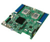
Intel® Server Board S5500WB TPS Appendix A: POST Code LED Decoder Appendix A: POST Code LED Decoder During the system boot process, the BIOS executes several platform configuration processes, each of which is assigned a specific hex POST code number. As each configuration routine is started, the BIOS displays the POST code on the POST code diagnostic LEDs found on the back edge of the server board. To assist in troubleshooting a system hang during the POST process, the diagnostic LEDs can be used to identify the last POST process to be executed. Each POST code is represented by the eight amber diagnostic LEDs. The POST codes are divided into two nibbles, an upper nibble and a lower nibble. The upper nibble bits are represented by diagnostic LEDs #4, #5, #6, and #7. The lower nibble bits are represented by diagnostics LEDs #0, #1, #2, and #3. If the bit is set in the upper and lower nibbles, then the corresponding LED is lit. If the bit is clear, then the corresponding LED is off. The diagnostic LED #7 is labeled as ―MSB‖ (Most Significant Bit), and the diagnostic LED #0 is labeled as ―LSB‖ (Least Significant Bit). Figure 33. Diagnostic LED Placement Diagram Revision 1.9 89 Intel order number E53971-008
-
 1
1 -
2
-
3
-
4
-
5
-
6
-
7
-
8
-
9
-
10
-
11
-
12
-
13
-
14
-
15
-
16
-
17
-
18
-
19
-
20
-
21
-
22
-
23
-
24
-
25
-
26
-
27
-
28
-
29
-
30
-
31
-
32
-
33
-
34
-
35
-
36
-
37
-
38
-
39
-
40
-
41
-
42
-
43
-
44
-
45
-
46
-
47
-
48
-
49
-
50
-
51
-
52
-
53
-
54
-
55
-
56
-
57
-
58
-
59
-
60
-
61
-
62
-
63
-
64
-
65
-
66
-
67
-
68
-
69
-
70
-
71
-
72
-
73
-
74
-
75
-
76
-
77
-
78
-
79
-
80
-
81
-
82
-
83
-
84
-
85
-
86
-
87
-
88
-
89
-
90
-
91
-
92
-
93
-
94
-
95
-
96
-
97
-
 98
98 -
 99
99 -
 100
100 -
 101
101 -
 102
102 -
 103
103 -
 104
104 -
 105
105 -
 106
106 -
 107
107 -
 108
108 -
109
-
110
-
111
-
112
-
113
-
114
-
115
-
116
-
117
 |
 |
