Intel S5500WB12V Product Specification - Page 92
Thermal Sensors
 |
View all Intel S5500WB12V manuals
Add to My Manuals
Save this manual to your list of manuals |
Page 92 highlights
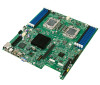
Design and Environmental Specifications Intel® Server Board S5500WB TPS Table 54. Fan Connector Location & Detail FAN_CPU2 CPU 2 FAN_CPU2A PWM_CPU0 PWM_CPU0 Tach 3 Tach 7 J3E1 J2J2 LED_Fan_Fault_CPU0 LED_Fan_Fault_CPU0A FAN_MEM2 Memory 2 FAN_MEM2R PWM_MEM0 PWM_MEM0 Tach 4 Tach 4 & 8 J2J1 J1D5 LED_Fan_Fault_MEM0 LED_Fan_Fault_MEM0R Figure 29. Fans and Sensors Block Diagram 9.2 Thermal Sensors 9.2.1 Processor PECI Temperature Sensor The processor thermal control uses a CPU PECI thermal sensor, which is a relative temperature off PROCHOT# trip point (a -20C reading means 20C below PROCHOT# trip point temperature). The BMC can get the processor PECI Tcontrol values for each CPU installed to use/follow the clamped algorithm for component thermal sensor. The following sample SDR settings could be used: Use Tcontrol (byte 8, bit 0 = 1): Tcontrol value is provided by BIOS via the Set CPU TControl command for the indicated CPU is used. 78 Revision 1.9 Intel order number E53971-008
-
 1
1 -
2
-
3
-
4
-
5
-
6
-
7
-
8
-
9
-
10
-
11
-
12
-
13
-
14
-
15
-
16
-
17
-
18
-
19
-
20
-
21
-
22
-
23
-
24
-
25
-
26
-
27
-
28
-
29
-
30
-
31
-
32
-
33
-
34
-
35
-
36
-
37
-
38
-
39
-
40
-
41
-
42
-
43
-
44
-
45
-
46
-
47
-
48
-
49
-
50
-
51
-
52
-
53
-
54
-
55
-
56
-
57
-
58
-
59
-
60
-
61
-
62
-
63
-
64
-
65
-
66
-
67
-
68
-
69
-
70
-
71
-
72
-
73
-
74
-
75
-
76
-
77
-
78
-
79
-
80
-
81
-
82
-
83
-
84
-
85
-
86
-
 87
87 -
 88
88 -
 89
89 -
 90
90 -
 91
91 -
 92
92 -
 93
93 -
 94
94 -
 95
95 -
 96
96 -
 97
97 -
98
-
99
-
100
-
101
-
102
-
103
-
104
-
105
-
106
-
107
-
108
-
109
-
110
-
111
-
112
-
113
-
114
-
115
-
116
-
117
 |
 |
