Intel S5500WB12V Product Specification - Page 40
Intel, Chipset IOH
 |
View all Intel S5500WB12V manuals
Add to My Manuals
Save this manual to your list of manuals |
Page 40 highlights
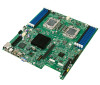
Functional Architecture Intel® Server Board S5500WB TPS Figure 18. Mirroring Memory Configuration 3.4.10 Memory Error LED Each DIMM is allocated an LED that, when lit, indicates a memory DIMM failure. It is the function of the BIOS to identify bad DIMMs during the boot process. The BIOS sends a message to the BMC to indicate which DIMM LED needs turn on. 3.5 Intel® 5500 Chipset IOH The Intel® 5500 Chipset component is an I/O Hub (IOH). The Intel® 5500 Chipset provides a connection point between various I/O components and Intel processors using the Intel® QPI interface. The Intel® 5500 Chipset IOH is capable of interfacing with up to 24 PCI Express* lanes, which can be configured in various combinations of x4, x8, x16 and limited x2 and x1 devices. The Intel® 5500 Chipset IOH is responsible for providing a path to the legacy bridge. In addition, the Intel® 5500 Chipset supports a x4 DMI (Direct Media Interface) link interface for the legacy bridge and interfaces with other devices through SMBus, Controller Link, and RMII (Reduced Media Independent Interface) manageability interfaces. The Intel® 5500 Chipset supports the following features and technologies: Intel® QuickPath Interconnect (Intel® QPI) PCI Express* Gen2 Intel® Virtualization Technology (Intel® VT) for Directed I/O 2 (Intel® VT-D2) Manageability Engine (ME) subsystem 3.5.1 IOH24D PCI Express* PCI Express* Gen1 and Gen2 are dual-simplex, point-to point serial differential low-voltage interconnects. The signaling bit rate is 2.5 Gb/s one direction per lane for Gen1 and 5.0 Gb/s one direction per lane for Gen2. Each port consists of a transmitter and receiver pair. A link between the ports of two devices is a collection of lanes (x1, x2, x4, x8, x16, and so forth). All lanes within a port must transmit data using the same frequency. The following table lists the usage of the IOH24D PCI Express* bus segments. 26 Revision 1.9 Intel order number E53971-008
-
 1
1 -
2
-
3
-
4
-
5
-
6
-
7
-
8
-
9
-
10
-
11
-
12
-
13
-
14
-
15
-
16
-
17
-
18
-
19
-
20
-
21
-
22
-
23
-
24
-
25
-
26
-
27
-
28
-
29
-
30
-
31
-
32
-
33
-
34
-
 35
35 -
 36
36 -
 37
37 -
 38
38 -
 39
39 -
 40
40 -
 41
41 -
 42
42 -
 43
43 -
 44
44 -
 45
45 -
46
-
47
-
48
-
49
-
50
-
51
-
52
-
53
-
54
-
55
-
56
-
57
-
58
-
59
-
60
-
61
-
62
-
63
-
64
-
65
-
66
-
67
-
68
-
69
-
70
-
71
-
72
-
73
-
74
-
75
-
76
-
77
-
78
-
79
-
80
-
81
-
82
-
83
-
84
-
85
-
86
-
87
-
88
-
89
-
90
-
91
-
92
-
93
-
94
-
95
-
96
-
97
-
98
-
99
-
100
-
101
-
102
-
103
-
104
-
105
-
106
-
107
-
108
-
109
-
110
-
111
-
112
-
113
-
114
-
115
-
116
-
117
 |
 |
