Intel S5500WB12V Product Specification - Page 75
VGA Connectors
 |
View all Intel S5500WB12V manuals
Add to My Manuals
Save this manual to your list of manuals |
Page 75 highlights
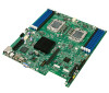
Intel® Server Board S5500WB TPS Connector/Header Locations and Pin-out Pin-Side B PCI Express* Spec Signal Description 13 GND 14 PETp(0) 15 PETn(0) 16 GND 17 Reserved 18 GND 19 PETp(1) 20 PETn(1) 21 GND 22 GND 23 PETp(2) 24 PETn(2) 25 GND 26 GND 27 PETp(3) 28 PETn(3) 29 GND 30 Reserved 31 PRSNT2# 32 GND 33 34 35 GND 36 GND 37 38 39 GND 40 GND 41 42 43 GND 44 GND 45 46 47 GND 48 PRSNT2# 49 GND 1X end 4X end 8X end Pin-Side A 13 14 15 16 17 18 19 20 21 22 23 24 25 26 27 28 29 30 31 32 33 34 35 36 37 38 39 40 41 42 43 44 45 46 47 48 49 PCI Express* Spec Signal REFCLK1+ REFCLK1+ GND PERp(0) PERn(0) GND Reserved GND PERp(1) PERn(1) GND GND PERp(2) PERn(2) GND GND PERp(3) PERn(3) GND Reserved Reserved GND GND GND GND GND GND GND GND Description 7.4.2 VGA Connectors The following table details the pin-out definition of the external VGA connector (J6A1): Pin 1 2 3 4 5 6 7 Table 39. VGA External Video Connector (J6A1) Signal Name V_IO_R_CONN V_IO_G_CONN V_IO_B_CONN TP_VID_CONN_B4 GND GND GND Description Red (analog color signal R) Green (analog color signal G) Blue (analog color signal B) No connection Ground Ground Ground Revision 1.9 61 Intel order number E53971-008
-
 1
1 -
2
-
3
-
4
-
5
-
6
-
7
-
8
-
9
-
10
-
11
-
12
-
13
-
14
-
15
-
16
-
17
-
18
-
19
-
20
-
21
-
22
-
23
-
24
-
25
-
26
-
27
-
28
-
29
-
30
-
31
-
32
-
33
-
34
-
35
-
36
-
37
-
38
-
39
-
40
-
41
-
42
-
43
-
44
-
45
-
46
-
47
-
48
-
49
-
50
-
51
-
52
-
53
-
54
-
55
-
56
-
57
-
58
-
59
-
60
-
61
-
62
-
63
-
64
-
65
-
66
-
67
-
68
-
69
-
 70
70 -
 71
71 -
 72
72 -
 73
73 -
 74
74 -
 75
75 -
 76
76 -
 77
77 -
 78
78 -
 79
79 -
 80
80 -
81
-
82
-
83
-
84
-
85
-
86
-
87
-
88
-
89
-
90
-
91
-
92
-
93
-
94
-
95
-
96
-
97
-
98
-
99
-
100
-
101
-
102
-
103
-
104
-
105
-
106
-
107
-
108
-
109
-
110
-
111
-
112
-
113
-
114
-
115
-
116
-
117
 |
 |
