JVC DT-3D24G1U DT-3D24G1U Operation Manual
JVC DT-3D24G1U Manual
 |
View all JVC DT-3D24G1U manuals
Add to My Manuals
Save this manual to your list of manuals |
JVC DT-3D24G1U manual content summary:
- JVC DT-3D24G1U | DT-3D24G1U Operation Manual - Page 1
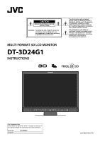
To reduce the risk of electric shock. Do not remove cover (or back). No user serviceable parts inside. Refer servicing to qualified service personnel. MULTI FORMAT 3D LCD MONITOR DT-3D24G1 INSTRUCTIONS The lightning flash with arrowhead symbol, within an equilateral triangle is intended to alert the - JVC DT-3D24G1U | DT-3D24G1U Operation Manual - Page 2
safeguards incorporated into this product, observe the following basic rules for its installation, use, and service. Please read these "IMPORTANT SAFEGUARDS" carefully before use. • All the safety and operating instructions should be read before the product is operated. • The safety and operating - JVC DT-3D24G1U | DT-3D24G1U Operation Manual - Page 3
CAUTION: Changes or modifications not approved by JVC could void the user's authority to operate with the instruction manual, may cause 14) Refer all servicing to qualified service personnel. Servicing is required when the discarding batteries, environmental problems must be considered and the local - JVC DT-3D24G1U | DT-3D24G1U Operation Manual - Page 4
directives and standards regarding electromagnetic compatibility and electrical safety. European representative of Victor Company of Japan, Limited is: JVC Technical Services Europe GmbH Postfach 10 05 04 61145 Friedberg Germany Information for Users on Disposal of Old Equipment [European Union - JVC DT-3D24G1U | DT-3D24G1U Operation Manual - Page 5
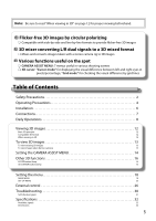
functions 16 SCOPE button/lamp 16 3D CURSOR button/lamp 16 Setting the menu 18 MAIN MENU 19 SET-UP MENU 23 External control 26 Troubleshooting 30 Self-check program 31 Specifications 32 Available signals 33 Dimensions 34 5 - JVC DT-3D24G1U | DT-3D24G1U Operation Manual - Page 6
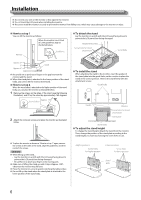
the removed screws and place the monitor as illustrated below. ● To install the stand When attaching the stand to the monitor, insert the guides of the stand plate into the guide holes on the monitor to place the stand in the correct position. Then fix the stand firmly with the attachment screws - JVC DT-3D24G1U | DT-3D24G1U Operation Manual - Page 7
sure to grasp its plug and pull it out. • DO NOT connect the power cord until all connections are complete. • Refer also to the user manual of each piece of equipment. 1 DC IN 24V terminal Terminal for DC 24V power supply (Voltage range: DC 23.3V − DC 25.5V). When using - JVC DT-3D24G1U | DT-3D24G1U Operation Manual - Page 8
Daily Operations Front panel Tally lamp This lamp is controlled by the tally function of the MAKE/TRIGGER terminal. • You can select the color of the tally lamp from "GREEN" or "RED." (→ "TALLY SELECT" in "FUNCTION SETTING" on page 23 and "External Control" on page 26) • "NO EFFECT" is displayed - JVC DT-3D24G1U | DT-3D24G1U Operation Manual - Page 9
5 MUTING button Turns off the sound when no menu screen is displayed (Muting). ● To cancel the function, press the button again or turn the VOLUME adjustment knob. ● Muting function is also canceled when "BALANCE" of "AUDIO SETTING" in the MAIN MENU is changed (→ page 21). 6 / / / buttons When a - JVC DT-3D24G1U | DT-3D24G1U Operation Manual - Page 10
Daily Operations (cont.) Audio Channel Selection Select audio channels emitted from the speakers (L/R) and the AUDIO MONITOR OUT(OUT1(L)/OUT2(R)) terminals, when EMBEDDED AUDIO signals come in to the SDI terminal and SDI input is selected. ● You have to choose a group of selectable audio channels - JVC DT-3D24G1U | DT-3D24G1U Operation Manual - Page 11
On the Status Display If you press the INPUT SELECT button (→ o on page 9) currently lit, the status of the input signal and setting of MUTING are displayed for about 3 seconds. ● Make the setting to display/hide the status in "STATUS DISPLAY" of the "INFORMATION." (→ page 24) ● When "STATUS DISPLAY - JVC DT-3D24G1U | DT-3D24G1U Operation Manual - Page 12
view flicker-free 3D images. Compatible 3D format The following 3D formats are supported: LINE BY LINE, SIDE BY SIDE HD, and SIDE BY SIDE SD with past experiences of PSS (Photo Sensitive Seizure) or users with heart problems, please consult a doctor before using this monitor. ● For children 6 and - JVC DT-3D24G1U | DT-3D24G1U Operation Manual - Page 13
To view 3D images To view in 3D, enter the 3D mode. The procedures differ between viewing existing 3D images and mixing L and R images taken by two cameras. To view existing 3D images View already 3D-processed images. 1 Input existing 3D images into the SDI IN 1/L, 2/R terminals or DVI-D terminal. ➔ - JVC DT-3D24G1U | DT-3D24G1U Operation Manual - Page 14
Setting the CAMERA ASSIST MENU This product is equipped with various camera rig adjustment assist functions for 3D viewing. Use the functions for camera adjustment in shooting. Menu Operations CAMERA ASSIST MENU 1 Press the CAMERA ASSIST button. ➔ The CAMERA ASSIST MENU appears. ● Only works - JVC DT-3D24G1U | DT-3D24G1U Operation Manual - Page 15
SPLIT L image is displayed on the left of the SPLIT line, and R image on the right. You can check the difference between the images from the two cameras. LR SEQ. Images for the left and right eyes are displayed alternately at 0.5-second interval. ● A marker appears on the upper part of the screen, - JVC DT-3D24G1U | DT-3D24G1U Operation Manual - Page 16
Other 3D functions SCOPE button/lamp You can display the wave form monitor or vector scope, and compare and check the SDI IN 1/L and SDI IN 2/R input signals. ● Works in MIX mode. The operation to be performed differs in other modes. (→ page 9) ● Each time you press the SCOPE button, the display - JVC DT-3D24G1U | DT-3D24G1U Operation Manual - Page 17
● In Cursor mode, the lines of the following two groups are displayed: Group A: L line/R line/H line (Normal: Green / Over the LIMIT: Red) Group B: L line/R line/H line (Normal: Magenta / Over the LIMIT: Orange) • You can change a group to display by pressing the SELECT button. Each time you press - JVC DT-3D24G1U | DT-3D24G1U Operation Manual - Page 18
display the MAIN MENU ➔ Press MENU button. To display the SET-UP MENU ➔ Press button while holding button. MAIN MENU Item being selected Operation guide SET-UP MENU 2 Press buttons to select an item, then press button. ● For some items, adjustments will be made by pressing . 3 Press buttons to - JVC DT-3D24G1U | DT-3D24G1U Operation Manual - Page 19
MAIN MENU PICTURE FUNCTION Setting for the picture quality. Item APERTURE *1 APERTURE LEVEL *1 Content Activates/deactivates the function at the level set in "APERTURE LEVEL." Simultaneously corrects the frequency characteristics of the RGB colors. Setting value OFF, ON 01 - 10 I/P MODE - JVC DT-3D24G1U | DT-3D24G1U Operation Manual - Page 20
Menu Configuration (cont.) ASPECT Setting value: 4:3, 16:9 Set the aspect ratio of images. ● Not activate when picture is displayed in the 1:1 mode. MARKER*1*2 Settings for marker functions. Item 1/2 AREA MARKER *3 MARKER ASPECT *3 SAFETY MARKER SAFETY AREA FRAME CENTER MARKER LINE BRIGHTNESS 2/2 - JVC DT-3D24G1U | DT-3D24G1U Operation Manual - Page 21
AUDIO SETTING Settings for the audio output balance, EMBEDDED AUDIO signals and level meter. Item BALANCE E.AUDIO GROUP *1 LEVEL METER SETTING *1 Content Adjust the balance between the right and left speakers. Select the audio channel group of the EMBEDDED AUDIO signals. The setting values and - JVC DT-3D24G1U | DT-3D24G1U Operation Manual - Page 22
Menu Configuration (cont.) SCOPE SETTING*1 Configure the settings for the wave form monitor and vector scope. Item GAIN SIZE *2 *3 POSITION *2 Content Adjust the input gain level. Set the window size. Select the window position. TRANSPARENT *3 AUTO OFF WAVE DISPLAY Make the background of the - JVC DT-3D24G1U | DT-3D24G1U Operation Manual - Page 23
SET-UP MENU FUNCTION SETTING Configure the sub menu display, the lighting color of the tally lamp, the size of images, the brightness of the button lamps. Item sub menu POSI. TALLY SELECT SD4:3 LARGE DIMMER Content Select the contents and displaying position of "sub menu." The setting values and - JVC DT-3D24G1U | DT-3D24G1U Operation Manual - Page 24
Menu Configuration (cont.) REMOTE SETTING (→ "External Control" on pages 26) Settings for the external control. Item SERIAL TYPE PARALLEL TYPE PIN1 PIN2 PIN3 PIN4 PIN5 PIN6 PIN7 PIN8 Content Select the input terminal used for external control by serial communication. Select the external control - JVC DT-3D24G1U | DT-3D24G1U Operation Manual - Page 25
CONTROL LOCK Setting value: OFF, VOL.LOCK, ALL LOCK Settings for disabling the buttons on the front panel. ● The following operations are not available when "VOL.LOCK" is selected. - VOLUME adjustment knob - Picture adjustment knob ● The "ALL LOCK" function disables to control the buttons on the - JVC DT-3D24G1U | DT-3D24G1U Operation Manual - Page 26
External control About the external control This monitor has three external control terminals. ● MAKE/TRIGGER terminal (RJ-45): The following external control systems are available. 1 MAKE (make contact) system: Controls the monitor by short-circuiting the corresponding pin terminal to the GND pin - JVC DT-3D24G1U | DT-3D24G1U Operation Manual - Page 27
Display Functions to be controlled TALLY SEL Selects the color of the tally lamp SDI 1/L Changes the input to "SDI 1/L" SDI 2/R Changes the input to "SDI 2/R" DVI Changes the input to "DVI" 3D Activates/Deactivates the 3D mode MIX 3D - JVC DT-3D24G1U | DT-3D24G1U Operation Manual - Page 28
External Control (cont.) Using the serial communication You can control the monitor from a personal computer etc. via the RS-485 or RS-232C terminal. ● Consult your dealer for the details of the external control specification. Input terminal RS-485 RS-232C Cable A - JVC DT-3D24G1U | DT-3D24G1U Operation Manual - Page 29
No. Commands 1 ! * **1 B C N 1 Cr 2 ! * **1 B C N 0 Cr 3 ! * **1 B I D S E T x x*2 Cr 4 ! * **1 B I D R E T Cr 5 ! * **1 B I D D S P x x*2 Cr Functions Starts communication (connection) Terminates communication (termination) Assigns the control ID Initializes the control - JVC DT-3D24G1U | DT-3D24G1U Operation Manual - Page 30
Troubleshooting Solutions to common problems related to the monitor are described here. If none of the solutions presented here solve the problem, unplug the monitor and consult an authorized dealer or service center. Symptom Probable cause and corrective action Page Cannot turn on the unit. No - JVC DT-3D24G1U | DT-3D24G1U Operation Manual - Page 31
Self-check program This monitor has a self-check function, which allows it to detect malfunctions and alert you. This makes troubleshooting easier. Whenever a problem occurs, one or some of the INPUT SELECT lamps will flash. If this happens, follow the steps below and contact your dealer to resolve - JVC DT-3D24G1U | DT-3D24G1U Operation Manual - Page 32
ratio Compliant video signal format Format Audio output Operation environment Power requirements Rated current External dimensions (excluding protruding parts) Mass Accessories DT-3D24G1 MULTI FORMAT 3D LCD MONITOR Type 24 wide format 16:10 → "Available signals" on page 33 3G SDI DUAL LINK HD - JVC DT-3D24G1U | DT-3D24G1U Operation Manual - Page 33
is precision equipment and needs dedicated packing material for transportation. Never use any packing material supplied from sources other than JVC or JVC-authorized dealers. ● For easy understanding, pictures and illustrations are emphasized, omitted or composed, and may be slightly different from - JVC DT-3D24G1U | DT-3D24G1U Operation Manual - Page 34
Specifications (cont.) Computer signals (preset) DVI-D (HDCP) terminals No. Signal name Resolution Horizontal Vertical Frequency Horizontal (kHz) Vertical (Hz) Scan system 1 VGA60 640 480 31.5 59.9 Non-interlace 2 WVGA60 852 480 31.5 59.9 Non-interlace 3 SVGA60 800 600 37.9 - JVC DT-3D24G1U | DT-3D24G1U Operation Manual - Page 35
- JVC DT-3D24G1U | DT-3D24G1U Operation Manual - Page 36
© 2011 Victor Company of Japan, Limited 0111SKH-MW-MT MULTI FORMAT 3D LCD MONITOR DT-3D24G1
-
 1
1 -
 2
2 -
 3
3 -
 4
4 -
 5
5 -
 6
6 -
 7
7 -
8
-
9
-
10
-
11
-
12
-
13
-
14
-
15
-
16
-
17
-
18
-
19
-
20
-
21
-
22
-
23
-
24
-
25
-
26
-
27
-
28
-
29
-
30
-
31
-
32
-
33
-
34
-
35
-
36
 |
 |
MULTI FORMAT 3D LCD MONITOR
DT-3D24G1
INSTRUCTIONS
LCT2655-001A-H
For Customer Use:
Enter below the Serial No. which is located on the rear of
the cabinet. Retain this information for future reference.
Model No.
:
DT-3D24G1
Serial No.
:
CAUTION:
To reduce the risk of electric shock. Do
not remove cover (or back). No user
serviceable parts inside. Refer servicing
to qualified service personnel.
RISK OF ELECTRICAL SHOCK
DO NOT OPEN
The lightning flash with arrowhead
symbol, within an equilateral triangle is
intended to alert the user to the presence
of uninsulated “dangerous voltage”
within the product’s enclosure that may
be of sufficient magnitude to constitute a
risk of electric shock to persons.
The exclamation point within an
equilateral triangle is intended to alert
the user to the presence of important
operating and maintenance (servicing)
instructions in the literature
accompanying the appliance.
CAUTION