JVC DT-3D24G1U DT-3D24G1U Operation Manual - Page 10
Daily Operations cont., Audio Channel Selection, On the Information Display
 |
View all JVC DT-3D24G1U manuals
Add to My Manuals
Save this manual to your list of manuals |
Page 10 highlights
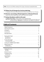
Daily Operations (cont.) Audio Channel Selection Select audio channels emitted from the speakers (L/R) and the AUDIO MONITOR OUT(OUT1(L)/OUT2(R)) terminals, when EMBEDDED AUDIO signals come in to the SDI terminal and SDI input is selected. ● You have to choose a group of selectable audio channels before the channel selection (→ "E.AUDIO GROUP" in "AUDIO SETTING" on page 21). ● The setting is memorized for each input (SDI 1/L and SDI 2/R). ● Works as SDI 1/L in MIX mode and DUAL LINK SDI input. 1 Press or button when a menu is not displayed. The screen for audio channel selection is displayed. ● The screen for audio channel selection automatically disappears in about 30 seconds after the previous operation. Audio channel selection screen Selected item 2 Press buttons to select the left (L ch) or right (R ch). 3 Press buttons to select an audio channel. ● Each time you press the button, the audio channel changes according to the settings of "E.AUDIO GROUP." (→ page 21) 4 Press MENU button. ● The screen for audio channel selection disappears. On the Information Display The monitor displays the information below. ● Configure the show/hide setting of each item in the menu. Use the T.C. button (→ r on page 9) to configure 5 and 6. ● Select the position of the information display (→ "POSITION" in "INFORMATION" on page 24). ● When any information of 1 2 3 or 4 above is displayed while signals come in from equipment other than a computer, the picture is displayed without overlapping the information display area. However, the information display will overlap with the picture when... - Displaying the picture with higher resolution than the resolution of the panel in 1:1 mode. - "SD4:3 LARGE" in the "FUNCTION SETTING" of SET-UP MENU is set to "ON." (→ page 23) 1 Audio level meter ● You can check the conditions of the EMBEDDED AUDIO signals when "LEVEL METER ch" is set to "LINE" or "DIVIDE." ● Not displayed when "LEVEL METER ch" is set to "OFF." (→ "AUDIO SETTING" on page 21) 2 Signal format ● Displayed when "STATUS DISPLAY" is set to "ON." (→ "INFORMATION" on page 24) ● For the contents displayed, see "Available signals" on page 33 and "On the signal format" on page 11. 3 Source name assigned in "CHARACTER SET." ● Displayed when "SOURCE ID" is set to "ON" or "AUTO." ● Displayed in large letters when "STATUS DISPLAY" is set to "OFF" or "AUTO." (→ "INFORMATION" on page 24) 4 CRC error indication ● Displayed when "CRC ERROR" is set to "ON." (→ "INFORMATION" on page 24) ● A red square is displayed when an error occurs. 5 Time code ● When the input signal includes no time code, "TC is displayed (→ r on page 9). 6 Time code (When the 3D button is "OFF" in MIX mode or the CAMERA ASSIST MENU is displayed) TC1: For SDI IN 1/L input signals TC2: For SDI IN 2/R input signals DIF: Difference of TC2 from TC1 ● When the CAMERA ASSIST MENU is "R SHIFT", the time code of SDI IN 1/L input signals is displayed in the 5 position. ● It is not displayed when the CAMERA ASSIST MENU is "ANAGLYPH." 10
-
 1
1 -
2
-
3
-
4
-
 5
5 -
 6
6 -
 7
7 -
 8
8 -
 9
9 -
 10
10 -
 11
11 -
 12
12 -
 13
13 -
 14
14 -
 15
15 -
16
-
17
-
18
-
19
-
20
-
21
-
22
-
23
-
24
-
25
-
26
-
27
-
28
-
29
-
30
-
31
-
32
-
33
-
34
-
35
-
36
 |
 |
