JVC DT-3D24G1U DT-3D24G1U Operation Manual - Page 24
Remote Setting, Information, Serial Type, Parallel Type, Position, Source Id, Character Set.
 |
View all JVC DT-3D24G1U manuals
Add to My Manuals
Save this manual to your list of manuals |
Page 24 highlights
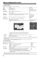
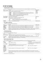
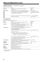
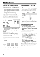
Menu Configuration (cont.) REMOTE SETTING (→ "External Control" on pages 26) Settings for the external control. Item SERIAL TYPE PARALLEL TYPE PIN1 PIN2 PIN3 PIN4 PIN5 PIN6 PIN7 PIN8 Content Select the input terminal used for external control by serial communication. Select the external control method for the MAKE/TRIGGER terminal. Assign the control functions to the pins of the MAKE/TRIGGER terminal. • Assign a function to each pin terminal by selecting "SET" in "PARALLEL TYPE" mentioned above. Setting value RS232C RS485 MAKE, TRIGGER, SET → on page 27. The functions are assigned for "PIN6" - "PIN8" and you cannot change the → "Using the MAKE/TRIGGER assignment of these functions. system" on page 26 INFORMATION Settings for the information display of the monitor. Item POSITION SOURCE ID CHARACTER SET. *1 Content Setting value Select the position to show the information display (→ "On the Information Display" on page 10). UPPER LOWER Select whether the name assigned in "CHARACTER SET." is displayed on the screen (→ "On the Information Display" on page 10). • When "AUTO" is selected, the display color synchronizes with the color of the tally lamp while the tally lamp is lit. OFF ON AUTO Assign a name to each video source as you like (10 characters at maximum). You can also enter a name using the RS-232C system. Setting of "CHARACTER SET." 1 Change the input to one that you want to assign a video source name for. 2 Select "CHARACTER SET." 3 Press the buttons to select a character to enter at first. ● Each time you press the button, the characters change in the following order. Press button to reverse the order. space STATUS DISPLAY TIME CODE 4 Press button to move the arrow to the next space. ● The characters entered before moving the arrow are memorized. 5 Repeat steps 3 and 4 (10 characters at maximum). 6 Press MENU button to store the name. Select whether the status of the current input and the setting of MUTING are displayed on the screen (→ "On the Status Display" on page 11). Select the type of the TIME CODE display. AUTO, OFF, ON VITC *2, LTC *2, D-VITC CRC ERROR Select whether the CRC error indication for the input HD SDI signal is OFF displayed on the screen (→ "On the Information Display" on page 10). ON SUB HOUR METER Display the hours of use (unit: hour). You can reset this item. MODEL VERSION Display the model name of the monitor. Display the version of the monitor. HOUR METER Display the total hours of use (unit: hour). This item is used for maintenance of the monitor. You cannot reset this item. *1 Memorized for each input. *2 Ancillary time code 24
-
 1
1 -
2
-
3
-
4
-
5
-
6
-
7
-
8
-
9
-
10
-
11
-
12
-
13
-
14
-
15
-
16
-
17
-
18
-
 19
19 -
 20
20 -
 21
21 -
 22
22 -
 23
23 -
 24
24 -
 25
25 -
 26
26 -
 27
27 -
 28
28 -
 29
29 -
30
-
31
-
32
-
33
-
34
-
35
-
36
 |
 |
