JVC DT-3D24G1U DT-3D24G1U Operation Manual - Page 22
Scope Setting, Sync Function, Wave Over Level
 |
View all JVC DT-3D24G1U manuals
Add to My Manuals
Save this manual to your list of manuals |
Page 22 highlights
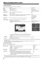
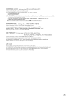
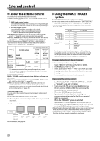
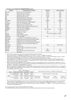
Menu Configuration (cont.) SCOPE SETTING*1 Configure the settings for the wave form monitor and vector scope. Item GAIN SIZE *2 *3 POSITION *2 Content Adjust the input gain level. Set the window size. Select the window position. TRANSPARENT *3 AUTO OFF WAVE DISPLAY Make the background of the window translucent. ON : Translucent OFF : Normal Set the function to turn off the window automatically 15 minutes after displayed. Select a wave form to be displayed for the wave form monitor. WAVE FILTER Turn on/off the lowpass filter to put over the input wave form data. WAVE OVER LEVEL *3 Set the over levels of the luminance signals (Y) and RGB signals. Example of the wave form monitor Ex.: When the luminance signal is Y, "MARKING" is set to "ON" and "LEVEL" is set to "080" Setting value -10 - +10 NORMAL, LARGE 1 (Lower right), 2 (Lower left) 3 (Upper left), 4 (Upper right) ON OFF ON, OFF Y, Pb, Pr (HD signal) Y, Cb, Cr (SD signal) R, G, B (RGB signal) FLAT (No filter) LOWPASS Example of the vector scope Ex.: When the color bar is displayed Red White Y - MARKING - LEVEL Image signals Start End • The wave form color of signals over the value specified in "LEVEL" turns red. • The display differs depending on the input signal or the "WAVE DISPLAY" setting. Turn on/off the function to change the wave form color of signals over the value specified in "LEVEL." (→ below) Adjust the lower limit for the over level. OFF, ON 070 - 109 *1 The wave form monitor is not displayed when the input signals are DVI (input from a computer). The vector scope is not displayed when the input signals are RGB. *2 When "SIZE" is set to "LARGE," the window is displayed in the center of the screen regardless of the "POSITION" setting. *3 Not displayed in MIX mode or when the CAMERA ASSIST button is "ON." SYNC FUNCTION Settings for the synchronization with signals. Item NO SYNC ACTION DELAY TIME LOW LATENCY Content Setting value Select the screen status when no signal is coming in. OFF STANDBY : The monitor is off (on standby) P.SAVE : Power save mode GRAY B. : Gray screen STANDBY P.SAVE GRAY B. Select the period until the screen status changes as selected in "NO SYNC ACTION" after 30sec., 5min., 15min. signals stop coming in. Activates/deactivates the function to shorten the time taken to display the picture. ON • If the picture is not displayed steadily while "ON" is selected, select "OFF." OFF • While "ON" is selected, the displayed picture may become unstable when an operation using buttons on the front panel or the menu is performed, or when the signal format changes. ● When setting "NO SYNC ACTION" to "GRAY B.," the screen color changes to gray and the power consumption of the back light is saved by half. Selecting "P.SAVE" (power save mode) saves more power consumption by turning off the back light. ● In the initial setting, "NO SYNC ACTION" is set to "P.SAVE", and "DELAY TIME" set to "15min." Change the settings if necessary. (U.S.A. only) 22
-
 1
1 -
2
-
3
-
4
-
5
-
6
-
7
-
8
-
9
-
10
-
11
-
12
-
13
-
14
-
15
-
16
-
 17
17 -
 18
18 -
 19
19 -
 20
20 -
 21
21 -
 22
22 -
 23
23 -
 24
24 -
 25
25 -
 26
26 -
 27
27 -
28
-
29
-
30
-
31
-
32
-
33
-
34
-
35
-
36
 |
 |
