JVC DT-3D24G1U DT-3D24G1U Operation Manual - Page 21
Audio Setting, Balance, E.audio Group, Level Meter Setting, Level Meter Ch, Bar Type, Reference Level
 |
View all JVC DT-3D24G1U manuals
Add to My Manuals
Save this manual to your list of manuals |
Page 21 highlights
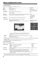
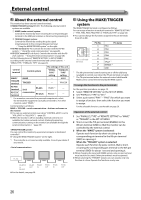
AUDIO SETTING Settings for the audio output balance, EMBEDDED AUDIO signals and level meter. Item BALANCE E.AUDIO GROUP *1 LEVEL METER SETTING *1 Content Adjust the balance between the right and left speakers. Select the audio channel group of the EMBEDDED AUDIO signals. The setting values and selectable audio channels of EMBEDDED AUDIO signals are as follows. 1G : Channel 1/2/3/4/1+2/3+4/1 - 4 (1G) 2G : Channel 5/6/7/8/5+6/7+8/5 - 8 (2G) 1-2G : Channel 1/2/3/4/5/6/7/8/1+2/3+4/5+6/7+8/1 - 4 (1G)/5 - 8 (2G)/1 - 8 (1G+2G) 3G : Channel 9/10/11/12/9+10/11+12/9 - 12 (3G) 1-3G : Channel 1/2/3/4/5/6/7/8/9/10/11/12/1+2/3+4/5+6/7+8/9+10/11+12/ 1 - 4 (1G)/5 - 8 (2G)/9 - 12 (3G)/1 - 8 (1G+2G)/1 - 12 (1-3G) • G means GROUP Adjust the level meter display for the EMBEDDED AUDIO signals. Example of the level meter display -Level meter position and audio channels Ex.: When "LEVEL METER ch" is set to "LINE" and "BAR TYPE" is set to "3COLORS" OVER LEVEL REFERENCE LEVEL Setting value L5 - L1, 0, R1 - R5 1G 2G 1-2G 3G 1-3G Red Yellow Green - LEVEL METER ch - BAR TYPE - REFERENCE LEVEL - OVER LEVEL • The level meter with no audio signal input is displayed in white for "3COLORS", and in gray for "W.100." • You can select the position of the level meter display-top or bottom of the screen (→ "POSITION" in "INFORMATION" on page 24). • When "PEAK HOLD" is set to "ON," the maximum level meter value will remain displayed for a set period of time. Select how the audio channels are displayed on the level meter. LINE DIVIDE : Displays the channels 1 - 6 at the left of the screen and 7 - 12 at the right. : Displays the odd channels at the left of the screen and the even channels at the right. OFF LINE DIVIDE Select the color of the level meter display. 3COLORS : Coloring for each level W.100 : White 3COLORS W.100 Select the standard input level indicated on the level meter. −20dB, −18dB Select the input level's lower limit indicated in red for the "3COLORS" display. −10dB, −8dB, −6dB, −4dB, −2dB - BAR BRIGHTNESS - PEAK HOLD Select the brightness of the level meter. Activates/deactivates the peak hold function of the level meter. LOW, HIGH OFF, ON *1 Memorized for each input. In MIX mode, the setting only applies to audio signals input into SDI IN 1/L. 21
-
 1
1 -
2
-
3
-
4
-
5
-
6
-
7
-
8
-
9
-
10
-
11
-
12
-
13
-
14
-
15
-
 16
16 -
 17
17 -
 18
18 -
 19
19 -
 20
20 -
 21
21 -
 22
22 -
 23
23 -
 24
24 -
 25
25 -
 26
26 -
27
-
28
-
29
-
30
-
31
-
32
-
33
-
34
-
35
-
36
 |
 |
