Kenmore 9787 Use and Care Guide - Page 13
Kenmore 9787 - Elite HE3 7.0 cu. Ft. Gas Dryer Manual
 |
View all Kenmore 9787 manuals
Add to My Manuals
Save this manual to your list of manuals |
Page 13 highlights
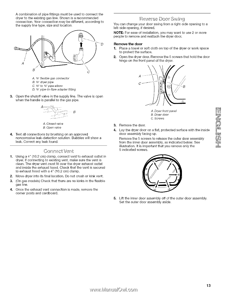
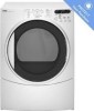
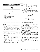
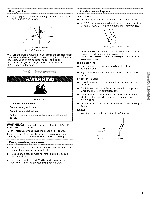
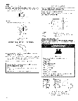
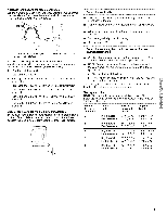
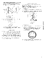
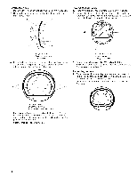
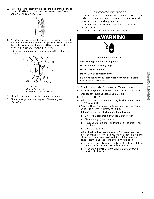
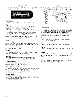
A combination of pipe fittings dryer to the existing gas line. connection. Your connection the supply line type, size and must be used to connect the Shown is a recommended may be different, according to location. You can change your door swing from a right-side left-side opening, if desired. opening to a NOTE: For ease of installation, you may want to use 2 or more people to remove and reattach the dryer door. ! Remove 1. 2. the door Place a towel or soft cloth on top of the dryer or work space to protect the surface. Open the dryer door. Remove the 5 screws that hold the door hinge on the front panel of the dryer. \ C A. _" flexible gas connector B. _" dryerpipe C. _" to _" pipe elbow D. _" pipe-to-flare adapter fitting 3, Open the shutoff valve in the supply line. The valve is open when the handle is parallel to the gas pipe. A. Dryer front panel B. Dryer door C. Screws A. Closed valve B. Open valve 4. 3, Remove the door. Lay the dryer door on a flat, protected surface with the inside door assembly facing up. Remove the 5 screws to release the outer door assembly from the inner door assembly, as indicated below. See illustration. It is important that you remove only the 5 indicated screws. 4. Test all connections by brushing on an approved noncorrosive leak-detection solution. Bubbles will show a leak. Correct any leak found. 1. Using a 4" (10.2 cm) clamp, connect vent to exhaust outlet in dryer. If connecting to existing vent, make sure the vent is clean. The dryer vent must fit over the dryer exhaust outlet and inside the exhaust hood. Check that the vent is secured to exhaust hood with a 4" (10.2 cm) clamp. Move dryer into its final location. Do not crush or kink vent. (On gas models) Check that there are no kinks in the flexible gas line. Once the exhaust vent connection corner posts and cardboard. is made, remove the 5, 2. 3. 4. Lift the inner door assembly off of the outer door assembly. Set the outer door assembly aside. 13
-
 1
1 -
2
-
3
-
4
-
5
-
6
-
7
-
 8
8 -
 9
9 -
 10
10 -
 11
11 -
 12
12 -
 13
13 -
 14
14 -
 15
15 -
 16
16 -
 17
17 -
 18
18 -
19
-
20
-
21
-
22
-
23
-
24
-
25
-
26
-
27
-
28
-
29
-
30
-
31
-
32
-
33
-
34
-
35
-
36
-
37
-
38
-
39
-
40
-
41
-
42
-
43
-
44
-
45
-
46
-
47
-
48
-
49
-
50
-
51
-
52
 |
 |