Lenovo 9935B3U User Manual - Page 19
Locating, parts, system, board
 |
UPC - 884343247403
View all Lenovo 9935B3U manuals
Add to My Manuals
Save this manual to your list of manuals |
Page 19 highlights
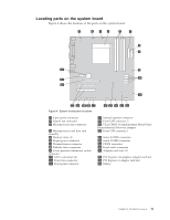
Locating parts on the system board Figure 4 shows the location of the parts on the system board. Figure 4. System board parts locations 1 4-pin power connector 2 System fan connector 3 Microprocessor fan connector 4 Microprocessor and heat sink assembly 5 Memory slots (4) 6 24-pin power connector 7 Thermal sensor connector 8 Diskette drive connector 9 Cover presence (Intrusion) switch connector 10 SATA connectors (4) 11 Power fan connector 12 Front panel connector 13 Internal speaker connector 14 Front USB connector 2 15 Clear CMOS (Complementary Metal-Oxide Semiconductor)/Recovery jumper 16 Front USB connector 1 17 Serial (COM2) connector 18 Serial (COMl) connector 19 CD-IN connector 20 Front audio connector 21 Adapter card slots (2) 22 PCI Express x16 graphics adapter card slot 23 PCI Express x1 adapter card slot 24 Battery Chapter 1. Product overview 11
-
 1
1 -
2
-
3
-
4
-
5
-
6
-
7
-
8
-
9
-
10
-
11
-
12
-
13
-
 14
14 -
 15
15 -
 16
16 -
 17
17 -
 18
18 -
 19
19 -
 20
20 -
 21
21 -
 22
22 -
 23
23 -
 24
24 -
25
-
26
-
27
-
28
-
29
-
30
-
31
-
32
-
33
-
34
-
35
-
36
-
37
-
38
-
39
-
40
-
41
-
42
-
43
-
44
-
45
-
46
-
47
-
48
-
49
-
50
-
51
-
52
-
53
-
54
-
55
-
56
-
57
-
58
-
59
-
60
-
61
-
62
-
63
-
64
-
65
-
66
-
67
-
68
-
69
-
70
-
71
-
72
-
73
-
74
-
75
-
76
-
77
-
78
-
79
-
80
-
81
-
82
-
83
-
84
 |
 |
