Lenovo 9935B3U User Manual - Page 46
Installing, security, features
 |
UPC - 884343247403
View all Lenovo 9935B3U manuals
Add to My Manuals
Save this manual to your list of manuals |
Page 46 highlights
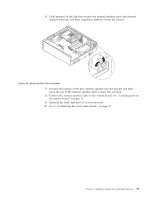
Important Correctly route all power supply cables to avoid interference with the drive bay assembly. Keep cables clear of the hinges and sides of the computer chassis. 3. If the drive bay assembly was removed, align it with the two slots and rails on the sides of the chassis and reconnect the drive cables to the system board. 4. Slide the drive bay assembly towards the rear of the chassis until it snaps into position. 5. Reinstall the front bezel if it was removed. 6. Position the computer cover on the chassis so that the rail guides on the sides of the cover engage the rails and push the cover to the closed position until it snaps into position. If your computer has screws that secure the computer cover, install the screws. Figure 37. Installing the computer cover 7. Install any locking devices such as a padlock as necessary. 8. Reconnect the external cables and power cords to the computer. See "Locating connectors on the rear of your computer" on page 8. 9. To update your configuration, refer to Chapter 4, "Using the Setup Utility," on page 51. Note: In most areas of the world, Lenovo requires the return of the defective CRU. Information about this will come with the CRU or will come a few days after the CRU arrives. Obtaining device drivers You can obtain device drivers for operating systems that are not preinstalled at: http://www.lenovo.com/support Installation instructions are provided in readme files with the device driver files. Installing security features To help prevent hardware theft and unauthorized access to your computer, several security options are available. In addition to physical locks, unauthorized use of your computer can be prevented by a software lock that locks the keyboard until a correct password is typed in. 38 User Guide
-
 1
1 -
2
-
3
-
4
-
5
-
6
-
7
-
8
-
9
-
10
-
11
-
12
-
13
-
14
-
15
-
16
-
17
-
18
-
19
-
20
-
21
-
22
-
23
-
24
-
25
-
26
-
27
-
28
-
29
-
30
-
31
-
32
-
33
-
34
-
35
-
36
-
37
-
38
-
39
-
40
-
 41
41 -
 42
42 -
 43
43 -
 44
44 -
 45
45 -
 46
46 -
 47
47 -
 48
48 -
 49
49 -
 50
50 -
 51
51 -
52
-
53
-
54
-
55
-
56
-
57
-
58
-
59
-
60
-
61
-
62
-
63
-
64
-
65
-
66
-
67
-
68
-
69
-
70
-
71
-
72
-
73
-
74
-
75
-
76
-
77
-
78
-
79
-
80
-
81
-
82
-
83
-
84
 |
 |
