Lenovo 9935B3U User Manual - Page 41
Replacing, system, assembly
 |
UPC - 884343247403
View all Lenovo 9935B3U manuals
Add to My Manuals
Save this manual to your list of manuals |
Page 41 highlights
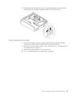
Note: You might have to gently twist the heat sink and fan assembly to free it from the microprocessor. 5. Lift the failing heat sink and fan assembly off the system board. 6. Remove the mylar film that covers the greased side of the new heat sink and fan assembly that will face the microprocessor. 7. Position the heat sink and fan assembly on the microprocessor socket and then position the clamp on the plastic retention bracket. Pivot the handle 1 to clamp the heat sink and fan assembly to the plastic retention bracket. Figure 32. Clamping the heat sink and fan assembly to the plastic retention bracket 8. Reconnect the heat sink and the fan assembly cable to the microprocessor fan connector on the system board. 9. Go to "Completing the parts replacement" on page 37. Replacing the system fan assembly Attention Do not open your computer or attempt any repair before reading and understanding the "Important safety information" in the ThinkCentre Safety and Warranty Guide that came with your computer. To obtain a copy of the ThinkCentre Safety and Warranty Guide, go to: http://www.lenovo.com/support This section provides instructions on how to replace the system fan assembly. To replace the system fan assembly: 1. Remove the computer cover. See "Removing the computer cover" on page 14. 2. Remove the front bezel and drive bay assembly. See "Accessing the system board components and drives" on page 15. 3. Disconnect the system fan assembly cable from the system board. See "Locating parts on the system board" on page 11. 4. Remove the hard disk drive. See "Replacing the hard disk drive" on page 26. Chapter 2. Installing options and replacing hardware 33
-
 1
1 -
2
-
3
-
4
-
5
-
6
-
7
-
8
-
9
-
10
-
11
-
12
-
13
-
14
-
15
-
16
-
17
-
18
-
19
-
20
-
21
-
22
-
23
-
24
-
25
-
26
-
27
-
28
-
29
-
30
-
31
-
32
-
33
-
34
-
35
-
 36
36 -
 37
37 -
 38
38 -
 39
39 -
 40
40 -
 41
41 -
 42
42 -
 43
43 -
 44
44 -
 45
45 -
 46
46 -
47
-
48
-
49
-
50
-
51
-
52
-
53
-
54
-
55
-
56
-
57
-
58
-
59
-
60
-
61
-
62
-
63
-
64
-
65
-
66
-
67
-
68
-
69
-
70
-
71
-
72
-
73
-
74
-
75
-
76
-
77
-
78
-
79
-
80
-
81
-
82
-
83
-
84
 |
 |
