Lenovo ThinkCentre M82 (English) User Guide - Page 47
Installing or replacing a memory module
 |
View all Lenovo ThinkCentre M82 manuals
Add to My Manuals
Save this manual to your list of manuals |
Page 47 highlights
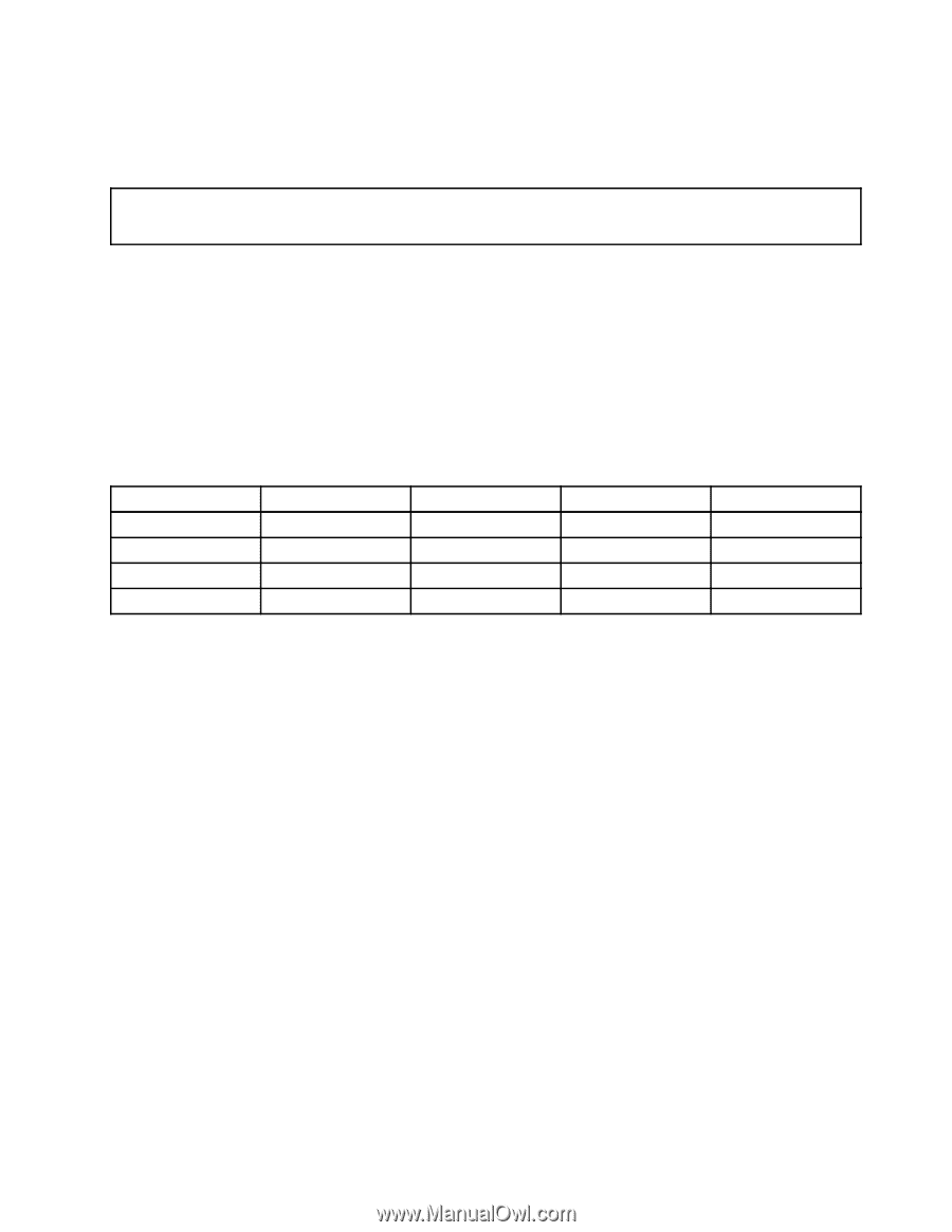
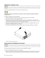
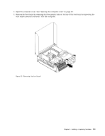
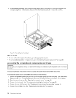
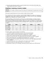
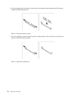
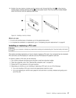
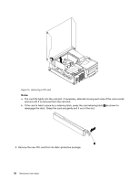
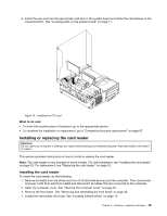
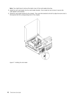
6. Pivot the optical drive bay upward to access the system board components and the cables. See "Replacing the optical drive" on page 56. Installing or replacing a memory module Attention: Do not open your computer or attempt any repair before reading and understanding the "Important safety information" on page v. This section provides instructions on how to install or replace a memory module. Your computer has four slots for installing or replacing DDR3 UDIMMs that provide up to a maximum of 32 GB system memory. When installing or replacing a memory module, use 2 GB, 4 GB, or 8 GB DDR3 UDIMMs in any combination up to a maximum of 32 GB. The following table provides information about the memory module installation rules that you should consider when installing or removing a memory module. The "X" mark indicates the memory slot(s) into which the memory module(s) should be installed in different situations. The numbers 1, 2, 3, and 4 indicate the installation sequence. To locate the memory module slots, see "Locating parts on the system board" on page 11. UDIMM One UDIMM Two UDIMMs Three UDIMMs Four UDIMMs DIMM 1 X, 3 X, 3 DIMM 2 X X, 1 X, 1 X, 1 DIMM 3 X, 4 DIMM 4 X, 2 X, 2 X, 2 To install or replace a memory module, do the following: 1. Turn off the computer and disconnect all power cords from electrical outlets. 2. Open the computer cover. See "Opening the computer cover" on page 32. 3. Remove the front bezel. See "Removing and reinstalling the front bezel" on page 32. 4. Remove the heat sink fan duct. See "Replacing the heat sink and fan assembly" on page 59. 5. Remove the hard disk drive. See "Replacing the hard disk drive" on page 54. 6. Pivot the optical drive bay upward to gain access to the memory slots. See "Replacing the optical drive" on page 56. 7. Locate the memory slots. See "Locating parts on the system board" on page 11. 8. Remove any parts that might prevent access to the memory slots. 9. Depending on whether you are installing or replacing a memory module, do one of the following: Chapter 5. Installing or replacing hardware 35
-
 1
1 -
2
-
3
-
4
-
5
-
6
-
7
-
8
-
9
-
10
-
11
-
12
-
13
-
14
-
15
-
16
-
17
-
18
-
19
-
20
-
21
-
22
-
23
-
24
-
25
-
26
-
27
-
28
-
29
-
30
-
31
-
32
-
33
-
34
-
35
-
36
-
37
-
38
-
39
-
40
-
41
-
 42
42 -
 43
43 -
 44
44 -
 45
45 -
 46
46 -
 47
47 -
 48
48 -
 49
49 -
 50
50 -
 51
51 -
 52
52 -
53
-
54
-
55
-
56
-
57
-
58
-
59
-
60
-
61
-
62
-
63
-
64
-
65
-
66
-
67
-
68
-
69
-
70
-
71
-
72
-
73
-
74
-
75
-
76
-
77
-
78
-
79
-
80
-
81
-
82
-
83
-
84
-
85
-
86
-
87
-
88
-
89
-
90
-
91
-
92
-
93
-
94
-
95
-
96
-
97
-
98
-
99
-
100
-
101
-
102
-
103
-
104
-
105
-
106
-
107
-
108
-
109
-
110
-
111
-
112
-
113
-
114
-
115
-
116
-
117
-
118
-
119
-
120
-
121
-
122
-
123
-
124
-
125
-
126
-
127
-
128
-
129
-
130
-
131
-
132
-
133
-
134
-
135
-
136
-
137
-
138
-
139
-
140
-
141
-
142
-
143
-
144
-
145
-
146
-
147
-
148
-
149
-
150
-
151
-
152
-
153
-
154
-
155
-
156
-
157
-
158
-
159
-
160
-
161
-
162
-
163
-
164
-
165
-
166
-
167
-
168
-
169
-
170
 |
 |