Lenovo ThinkCentre M82 (English) User Guide - Page 73
then fully tighten screw
 |
View all Lenovo ThinkCentre M82 manuals
Add to My Manuals
Save this manual to your list of manuals |
Page 73 highlights
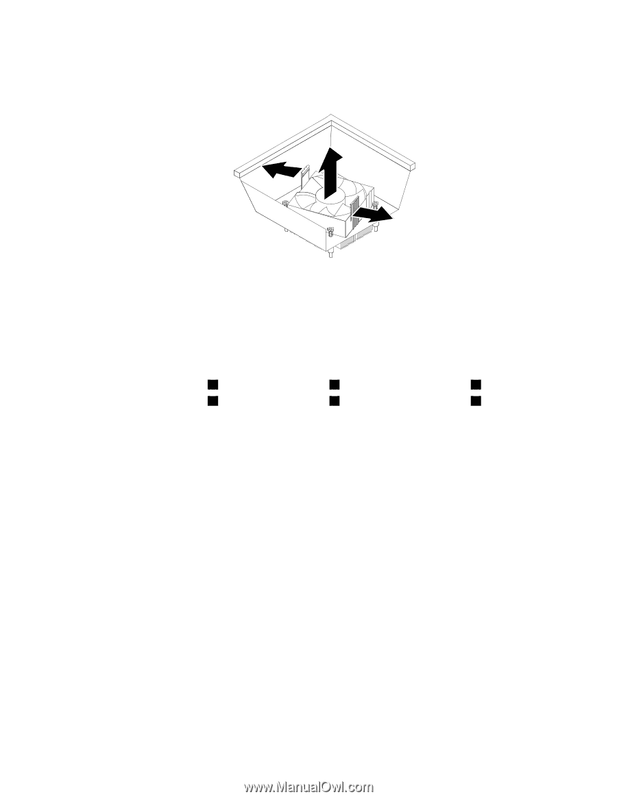
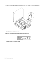
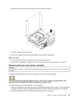
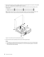
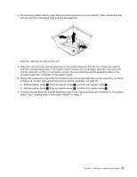
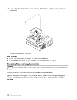
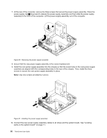
6. Pivot the two plastic retaining clips that secure the heat sink fan duct outward. Then remove the heat sink fan duct from the failing heat sink and fan assembly. Figure 46. Removing the heat sink fan duct 7. Place the new heat sink and fan assembly on the system board so that the four screws are aligned with the corresponding holes in the system board. Ensure that you properly place the new heat sink and fan assembly so that you can easily connect the new heat sink and fan assembly cable to the microprocessor fan connector on the system board. 8. Follow this sequence to install the four screws to secure the new heat sink and fan assembly, as shown in Figure 45 "Screws that secure the heat sink and fan assembly" on page 60: a. Partially tighten screw 1 , then fully tighten screw 2 , and then fully tighten screw 1 . b. Partially tighten screw 3 , then fully tighten screw 4 , and then fully tighten screw 3 . 9. Connect the new heat sink and fan assembly cable to the microprocessor fan connector on the system board. See "Locating parts on the system board" on page 11. Chapter 5. Installing or replacing hardware 61
-
 1
1 -
2
-
3
-
4
-
5
-
6
-
7
-
8
-
9
-
10
-
11
-
12
-
13
-
14
-
15
-
16
-
17
-
18
-
19
-
20
-
21
-
22
-
23
-
24
-
25
-
26
-
27
-
28
-
29
-
30
-
31
-
32
-
33
-
34
-
35
-
36
-
37
-
38
-
39
-
40
-
41
-
42
-
43
-
44
-
45
-
46
-
47
-
48
-
49
-
50
-
51
-
52
-
53
-
54
-
55
-
56
-
57
-
58
-
59
-
60
-
61
-
62
-
63
-
64
-
65
-
66
-
67
-
 68
68 -
 69
69 -
 70
70 -
 71
71 -
 72
72 -
 73
73 -
 74
74 -
 75
75 -
 76
76 -
 77
77 -
 78
78 -
79
-
80
-
81
-
82
-
83
-
84
-
85
-
86
-
87
-
88
-
89
-
90
-
91
-
92
-
93
-
94
-
95
-
96
-
97
-
98
-
99
-
100
-
101
-
102
-
103
-
104
-
105
-
106
-
107
-
108
-
109
-
110
-
111
-
112
-
113
-
114
-
115
-
116
-
117
-
118
-
119
-
120
-
121
-
122
-
123
-
124
-
125
-
126
-
127
-
128
-
129
-
130
-
131
-
132
-
133
-
134
-
135
-
136
-
137
-
138
-
139
-
140
-
141
-
142
-
143
-
144
-
145
-
146
-
147
-
148
-
149
-
150
-
151
-
152
-
153
-
154
-
155
-
156
-
157
-
158
-
159
-
160
-
161
-
162
-
163
-
164
-
165
-
166
-
167
-
168
-
169
-
170
 |
 |