Lexmark 11C0200 Service Manual - Page 208
Lexmark 11C0200 - Optra SC 1275 Color Laser Printer Manual
 |
UPC - 734646126885
View all Lexmark 11C0200 manuals
Add to My Manuals
Save this manual to your list of manuals |
Page 208 highlights
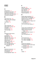
Index A abbreviations 1-2 ac power service check 2-40 adjustment procedures 3-3 AIDC sensor and erase lamp 1-11 attendance messages 2-11 F flash test 2-58 frames 2 assembly 5-10 fuser assembly 5-38 fuser removal 3-8 fuser service check 2-33 fuser/exit assembly 5-42 H handling laser equipment 3-3 handling PWBs with MOISICS 3-1 handling the drum cartridge 3-2 heater lamp removal 3-10 high voltage/sub high voltage board removal 3-12 housing assembly 5-2 how to use the parts catalog 5-1 B base sensor test 2-56 basic printer paper passage test 2-48 button test 2-51 C clean engine test 2-51 clearing the error log 2-59 connectors 4-18 controller card 5-54 cover removals 3-5 I image quality troubleshooting 2-42 image transfer belt removal 3-7 image transfer belt service check 2-35 image transfer roller removal 3-6 initial check 2-1 input tray sensor test 2-55 D developing motor service check 2-34 development 1-10 diagnostic aids 2-48 diagnostic menu group 2-48 diagnostic mode 2-48 disk test/clean 2-57 DRAM memory test 2-51 drive assembly 5-14 drum cartridge removal 3-6 drum cartridge toner full detection 1-6 L LCD hardware test 2-51 line 1 status messages 2-3 line 2 status messages 2-10 M maintenance approach 1-1 mechanical controller board frame removal 3-19 mechanical controller board removal 3-14 E electrical components 4-12 electrical parts 5-46 exit assembly 5-44 exiting diagnostic mode 2-59 N notices viii Index X-1
-
 1
1 -
2
-
3
-
4
-
5
-
6
-
7
-
8
-
9
-
10
-
11
-
12
-
13
-
14
-
15
-
16
-
17
-
18
-
19
-
20
-
21
-
22
-
23
-
24
-
25
-
26
-
27
-
28
-
29
-
30
-
31
-
32
-
33
-
34
-
35
-
36
-
37
-
38
-
39
-
40
-
41
-
42
-
43
-
44
-
45
-
46
-
47
-
48
-
49
-
50
-
51
-
52
-
53
-
54
-
55
-
56
-
57
-
58
-
59
-
60
-
61
-
62
-
63
-
64
-
65
-
66
-
67
-
68
-
69
-
70
-
71
-
72
-
73
-
74
-
75
-
76
-
77
-
78
-
79
-
80
-
81
-
82
-
83
-
84
-
85
-
86
-
87
-
88
-
89
-
90
-
91
-
92
-
93
-
94
-
95
-
96
-
97
-
98
-
99
-
100
-
101
-
102
-
103
-
104
-
105
-
106
-
107
-
108
-
109
-
110
-
111
-
112
-
113
-
114
-
115
-
116
-
117
-
118
-
119
-
120
-
121
-
122
-
123
-
124
-
125
-
126
-
127
-
128
-
129
-
130
-
131
-
132
-
133
-
134
-
135
-
136
-
137
-
138
-
139
-
140
-
141
-
142
-
143
-
144
-
145
-
146
-
147
-
148
-
149
-
150
-
151
-
152
-
153
-
154
-
155
-
156
-
157
-
158
-
159
-
160
-
161
-
162
-
163
-
164
-
165
-
166
-
167
-
168
-
169
-
170
-
171
-
172
-
173
-
174
-
175
-
176
-
177
-
178
-
179
-
180
-
181
-
182
-
183
-
184
-
185
-
186
-
187
-
188
-
189
-
190
-
191
-
192
-
193
-
194
-
195
-
196
-
197
-
198
-
199
-
200
-
201
-
202
-
 203
203 -
 204
204 -
 205
205 -
 206
206 -
 207
207 -
 208
208 -
 209
209
 |
 |
