Lexmark 11C0200 Service Manual - Page 22
Lexmark 11C0200 - Optra SC 1275 Color Laser Printer Manual
 |
UPC - 734646126885
View all Lexmark 11C0200 manuals
Add to My Manuals
Save this manual to your list of manuals |
Page 22 highlights
1. General Information Maintenance Approach The diagnostic information in this manual leads you to the correct field replaceable unit (FRU) or part. Use the error code charts, symptom index, and service checks to determine the symptom and repair the failure. After you complete the repair, perform tests as needed to verify the repair. Tools The removal and adjustment procedures described in this manual require the following tools and equipment: Magnetic tip Phillips screwdrivers, large and small Flat-blade screwdriver Analog volt ohmmeter (a digital volt ohmmeter may also be used) Needle nose pliers When you make voltage readings, always use frame ground unless another ground is specified. General Information 1-1
-
 1
1 -
2
-
3
-
4
-
5
-
6
-
7
-
8
-
9
-
10
-
11
-
12
-
13
-
14
-
15
-
16
-
 17
17 -
 18
18 -
 19
19 -
 20
20 -
 21
21 -
 22
22 -
 23
23 -
 24
24 -
 25
25 -
 26
26 -
 27
27 -
28
-
29
-
30
-
31
-
32
-
33
-
34
-
35
-
36
-
37
-
38
-
39
-
40
-
41
-
42
-
43
-
44
-
45
-
46
-
47
-
48
-
49
-
50
-
51
-
52
-
53
-
54
-
55
-
56
-
57
-
58
-
59
-
60
-
61
-
62
-
63
-
64
-
65
-
66
-
67
-
68
-
69
-
70
-
71
-
72
-
73
-
74
-
75
-
76
-
77
-
78
-
79
-
80
-
81
-
82
-
83
-
84
-
85
-
86
-
87
-
88
-
89
-
90
-
91
-
92
-
93
-
94
-
95
-
96
-
97
-
98
-
99
-
100
-
101
-
102
-
103
-
104
-
105
-
106
-
107
-
108
-
109
-
110
-
111
-
112
-
113
-
114
-
115
-
116
-
117
-
118
-
119
-
120
-
121
-
122
-
123
-
124
-
125
-
126
-
127
-
128
-
129
-
130
-
131
-
132
-
133
-
134
-
135
-
136
-
137
-
138
-
139
-
140
-
141
-
142
-
143
-
144
-
145
-
146
-
147
-
148
-
149
-
150
-
151
-
152
-
153
-
154
-
155
-
156
-
157
-
158
-
159
-
160
-
161
-
162
-
163
-
164
-
165
-
166
-
167
-
168
-
169
-
170
-
171
-
172
-
173
-
174
-
175
-
176
-
177
-
178
-
179
-
180
-
181
-
182
-
183
-
184
-
185
-
186
-
187
-
188
-
189
-
190
-
191
-
192
-
193
-
194
-
195
-
196
-
197
-
198
-
199
-
200
-
201
-
202
-
203
-
204
-
205
-
206
-
207
-
208
-
209
 |
 |

General Information 1-1
1.
General Information
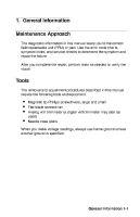
Maintenance Approach
The diagnostic information in this manual leads you to the correct
field replaceable unit (FRU) or part. Use the error code charts,
symptom index, and service checks to determine the symptom and
repair the failure.
After you complete the repair, perform tests as needed to verify the
repair.
Tools
The removal and adjustment procedures described in this manual
require the following tools and equipment:
•
Magnetic tip Phillips screwdrivers, large and small
•
Flat-blade screwdriver
•
Analog volt ohmmeter (a digital volt ohmmeter may also be
used)
•
Needle nose pliers
When you make voltage readings, always use frame ground unless
another ground is specified.