Marantz AV8003 AV8003 User Manua - Page 11
Audio In/out Tv, Dvd, Vcr1 - zone
 |
View all Marantz AV8003 manuals
Add to My Manuals
Save this manual to your list of manuals |
Page 11 highlights
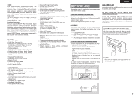
NAMES AND FUNCTION CONNECTIONS SETUP BASIC OPERATION ENGLISH @1 ZONE REMOTE IN/OUT terminals IN: Connect to a zone remote control device, available from your Marantz dealer. OUT: Connect to the Marantz component equipped with remote control (RC-5) terminals in Multi zone. @2 REMOTE CONT. IN/OUT terminals Connect to a Marantz component equipped with remote control (RC-5) terminals. @3 AUDIO IN/OUT (TV, DVD, VCR1, DSS/VCR2, TAPE, CD/CDR) These are the analog audio inputs and outputs. There are 6 audio inputs and 4 audio outputs. The audio jacks are nominally labeled for cassette tape decks, compact disc players, DVD players and etc.... The audio inputs and outputs require RCA-type connectors. @4 DIGITAL INPUT (Dig.1 - 6) / OUTPUT (coaxial, optical) These are the digital audio inputs and outputs. There are 3 digital inputs with coaxial jacks, 3 with optical jacks. The inputs accept digital audio signals from a CD, DVD, or other digital source component. For digital output, there is 1 coaxial output and 1 optical output. The digital outputs can be connected to MD recorders, CD recorders, or other similar components. @5 VIDEO IN/OUT (TV, DVD, VCR1, DSS/VCR2) These are the video inputs and outputs. There are 4 video inputs and 2 video outputs and each one includes both composite video and S-video configurations. Connect VCRs, DVD players, and other video components to the video inputs. The 2 video output channels can be used to be connected to video tape recorders for making recordings. @6 HDMI INPUT / OUTPUT This unit has 4 HDMI inputs and 2 HDMI output. The input function can be selected from the OSD menu system. (See page 24) REMOTE CONTROLLER RC2001 The provided remote controller is a universal remote controller. The POWER button, numeric buttons and control buttons are used in common across different input source components. You can use the Wizz.it3 editing software to select your favorite settings for the buttons and pages of the remote controller. z x c v v b n . m , . ⁄0 z POWER ON and OFF buttons These buttons are used when controlling devices that have been set with separately powered on and off remote commands. x SOURCE ON/OFF button This button is used when controlling devices that have been set with a single power on/off remote command. c LCD Display Remote controller display v Programmable soft buttons These buttons are used by the Wizz.it 3 editor software to make LCD display and button operation settings. These buttons are also used to adjust the number of pages for each device. b Page Scroll buttons These buttons are used when scrolling pages in Home mode and the device modes. n Home button This button is used to select Home mode. To select a device that will be controlled, first select Home mode, then select the device. m Light button This button is used to turn on the backlight for the buttons and LCD. , Cursor, ENTER buttons . Programmable Hard buttons These buttons are used by the Wizz.it 3 editor software to make the remote controller command settings for learning and macro operations. ⁄0 USB port This port is used to connect the remote controller and a PC with the supplied USB cable to enable editing with the Wizz.it 3 editor software. RC2001 LCD INDICATORS A B C D A Mode display area Home: This is displayed during Home mode. Device Name: This displays the device mode name that is currently active. This area is always highlighted. B Command display area This displays the information that has been set for the display items in the device modes. C Battery indicator This displays the remaining battery power. D Sub info. Area Normal operation: The page number that has been set for the respective mode is displayed. When sending IR command: The command name that has been set for the respective button is highlighted. Operation when not sending an IR command (such as jump operation): The operation name that has been set for the button is displayed normally (not highlighted). ADVANCED OPERATION REMOTE CONTROLLER TROUBLESHOOTING OTHERS 8
-
 1
1 -
2
-
3
-
4
-
5
-
 6
6 -
 7
7 -
 8
8 -
 9
9 -
 10
10 -
 11
11 -
 12
12 -
 13
13 -
 14
14 -
 15
15 -
 16
16 -
17
-
18
-
19
-
20
-
21
-
22
-
23
-
24
-
25
-
26
-
27
-
28
-
29
-
30
-
31
-
32
-
33
-
34
-
35
-
36
-
37
-
38
-
39
-
40
-
41
-
42
-
43
-
44
-
45
-
46
-
47
-
48
-
49
-
50
-
51
-
52
-
53
-
54
-
55
-
56
-
57
-
58
-
59
-
60
-
61
-
62
-
63
-
64
-
65
-
66
-
67
-
68
-
69
-
70
-
71
-
72
-
73
-
74
-
75
-
76
-
77
-
78
-
79
-
80
-
81
-
82
-
83
-
84
-
85
-
86
-
87
-
88
-
89
-
90
-
91
-
92
-
93
-
94
-
95
-
96
-
97
-
98
-
99
-
100
-
101
-
102
-
103
-
104
-
105
-
106
-
107
 |
 |
