Motorola WR850G User Guide - Page 19
Mounting Template appears., Print
 |
UPC - 612572095027
View all Motorola WR850G manuals
Add to My Manuals
Save this manual to your list of manuals |
Page 19 highlights
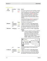
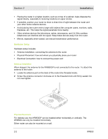
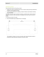
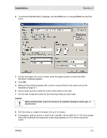
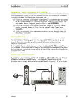
Installation Section 2 2 To print the Wall Mounting Template, click the Print icon or choose Print from the File menu. 3 In both the Pages from and to fields, enter the page number on which the Wall Mounting Template appears. 4 Click OK. 5 Measure the printed template with a ruler to ensure that it is the same size as the template on page 2-3. 6 Use a center punch to mark the center of the holes on the wall. 7 On the wall, locate the marks for the mounting holes you just made. WARNING! Before drilling holes, check the structure for potential damage to water, gas, or electric lines. 8 Drill the holes to a depth of at least 3.8 cm (11⁄2 inches). 9 If necessary, seat an anchor in each hole. Use M5 x 38 mm (#10-16 x 11/2 inch) screws with a flat underside and maximum screw head diameter of 10.5 mm to mount the router. WR850 2-5
-
 1
1 -
2
-
3
-
4
-
5
-
6
-
7
-
8
-
9
-
10
-
11
-
12
-
13
-
 14
14 -
 15
15 -
 16
16 -
 17
17 -
 18
18 -
 19
19 -
 20
20 -
 21
21 -
 22
22 -
 23
23 -
 24
24 -
25
-
26
-
27
-
28
-
29
-
30
-
31
-
32
-
33
-
34
-
35
-
36
-
37
-
38
-
39
-
40
-
41
-
42
-
43
-
44
-
45
-
46
-
47
-
48
-
49
-
50
-
51
-
52
-
53
-
54
-
55
-
56
-
57
-
58
-
59
-
60
-
61
-
62
-
63
-
64
-
65
-
66
-
67
-
68
-
69
-
70
-
71
-
72
-
73
-
74
-
75
-
76
-
77
-
78
-
79
-
80
-
81
-
82
-
83
-
84
-
85
-
86
-
87
-
88
-
89
-
90
-
91
-
92
-
93
-
94
-
95
-
96
-
97
-
98
-
99
-
100
-
101
-
102
-
103
-
104
-
105
-
106
-
107
-
108
-
109
-
110
-
111
-
112
-
113
-
114
-
115
-
116
-
117
-
118
-
119
-
120
-
121
-
122
-
123
 |
 |
