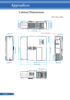
NEC NP-PE401H User's Manual - Page 82
Pin Assignments of D-Sub COMPUTER Input Connector
 |
View all NEC NP-PE401H manuals
Add to My Manuals
Save this manual to your list of manuals |
Page 82 highlights
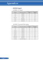
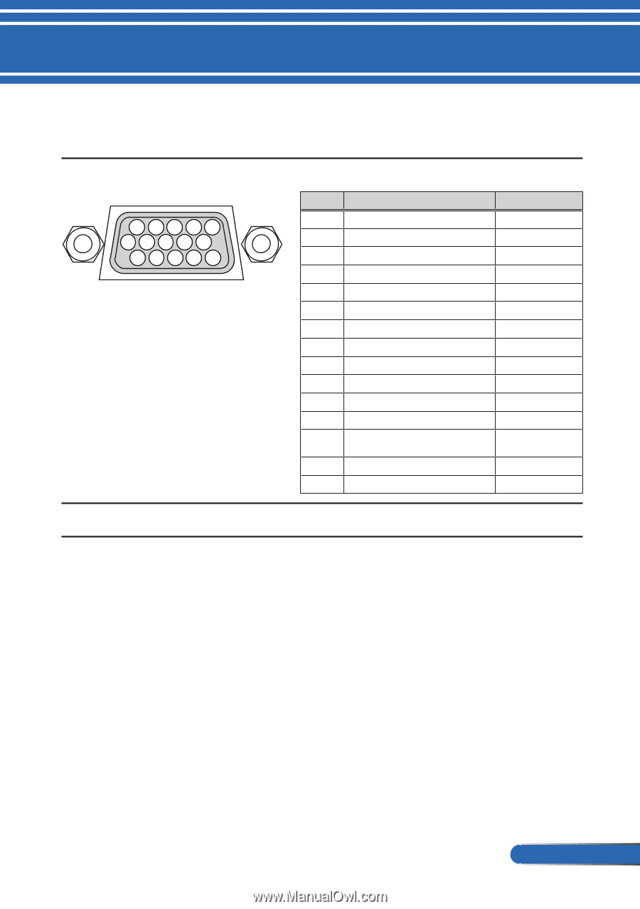
Appendices Pin Assignments of D-Sub COMPUTER Input Connector Mini D-Sub 15 Pin Connector 11 12 13 14 15 6 7 8 9 10 12345 Signal Level Video signal : 0.7Vp-p (Analog) Sync signal : TTL level Pin No. 1 2 3 4 5 6 7 8 9 10 11 12 13 14 15 RGB Signal (Analog) Red Green Blue Ground Ground Red Ground Green Gro Blue Ground No Connection Sync Signal Ground No Connection Bi-directional DATA (SDA) Horizontal Sync or Composite Sync Vertical Sync Data Clock YCbCr Signal Cr Y Cb Cr Ground Y Ground Cb Ground COMPUTER IN NOTE: Pin Nos. 12 and 15 are required for DDC/CI. 75 ... English
-
 1
1 -
2
-
3
-
4
-
5
-
6
-
7
-
8
-
9
-
10
-
11
-
12
-
13
-
14
-
15
-
16
-
17
-
18
-
19
-
20
-
21
-
22
-
23
-
24
-
25
-
26
-
27
-
28
-
29
-
30
-
31
-
32
-
33
-
34
-
35
-
36
-
37
-
38
-
39
-
40
-
41
-
42
-
43
-
44
-
45
-
46
-
47
-
48
-
49
-
50
-
51
-
52
-
53
-
54
-
55
-
56
-
57
-
58
-
59
-
60
-
61
-
62
-
63
-
64
-
65
-
66
-
67
-
68
-
69
-
70
-
71
-
72
-
73
-
74
-
75
-
76
-
 77
77 -
 78
78 -
 79
79 -
 80
80 -
 81
81 -
 82
82 -
 83
83 -
 84
84 -
 85
85 -
 86
86 -
 87
87
 |
 |
75
... English
Appendices
Pin Assignments of D-Sub COMPUTER Input
Connector
Mini D-Sub 15 Pin Connector
1
2
3
4
5
11 12 13 14 15
6
7
8
9
10
Signal Level
Video signal : 0.7Vp-p (Analog)
Sync signal : TTL level
COMPUTER IN
NOTE: Pin Nos. 12 and 15 are required for DDC/CI.
Pin No.
RGB Signal (Analog)
YCbCr Signal
1
Red
Cr
2
Green
Y
3
Blue
Cb
4
Ground
5
Ground
6
Red Ground
Cr Ground
7
Green Gro
Y Ground
8
Blue Ground
Cb Ground
9
No Connection
10
Sync Signal Ground
11
No Connection
12
Bi-directional DATA (SDA)
13
Horizontal Sync or Composite
Sync
14
Vertical Sync
15
Data Clock