Netgear GS752TS GS7xxTS-TPS Hardware Installation Guide
Netgear GS752TS Manual
 |
View all Netgear GS752TS manuals
Add to My Manuals
Save this manual to your list of manuals |
Netgear GS752TS manual content summary:
- Netgear GS752TS | GS7xxTS-TPS Hardware Installation Guide - Page 1
GS728TS, GS728TPS, GS752TS, and GS752TPS Smart Switch Hardware Installation Guide 350 East Plumeria Drive San Jose, CA 95134 USA January 2012 202-10994-01 v1.0 - Netgear GS752TS | GS7xxTS-TPS Hardware Installation Guide - Page 2
GS728TS, GS728TPS, GS752TS, and GS752TPS Smart Switch Hardware Installation Guide ©2012 NETGEAR, Inc. All rights reserved No part of this publication may be reproduced, transmitted, transcribed, stored in a retrieval system, or translated into any language in any - Netgear GS752TS | GS7xxTS-TPS Hardware Installation Guide - Page 3
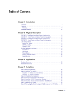
Chapter 1 Introduction Overview 7 Features 7 Stacking 9 Package Contents 10 Chapter 2 Physical Description GS728TS Front-Panel and Back-Panel Configuration 12 GS728TPS Front-Panel and Back-Panel Configuration 13 GS752TS Front-Panel and Back-Panel Configuration 15 GS752TPS Front-Panel and Back - Netgear GS752TS | GS7xxTS-TPS Hardware Installation Guide - Page 4
GS728TS, GS728TPS, GS752TS, and GS752TPS Smart Switch Hardware Installation Guide Appendix A Troubleshooting Troubleshooting Chart 31 Additional Troubleshooting Suggestions 32 Network Adapter Cards 32 Configuration 32 Switch Integrity 32 Auto-Negotiation 32 Appendix B Technical Specifications - Netgear GS752TS | GS7xxTS-TPS Hardware Installation Guide - Page 5
GS728TS, GS728TPS, GS752TS, and GS752TPS Smart Switch Hardware Installation Guide Contents | 5 - Netgear GS752TS | GS7xxTS-TPS Hardware Installation Guide - Page 6
purchase of your NETGEAR® ProSafeTM GS728TS, GS728TPS, GS752TS, or GS752TPS Smart Switch! Your Smart Switch is a state stacking. The GS728TS, GS728TPS, GS752TS, and GS752TPS Smart Switch Hardware Installation Guide describes how to install and power on the Smart Switch. The information in this manual - Netgear GS752TS | GS7xxTS-TPS Hardware Installation Guide - Page 7
to six switches in a stack to create a high-port-capacity solution with a single point of administration The NETGEAR GS728TS, GS728TPS, GS752TS, or GS752TPS Smart Switch also provides the benefit of administrative management with a complete package of features for the observation, configuration, and - Netgear GS752TS | GS7xxTS-TPS Hardware Installation Guide - Page 8
SFP slots and two 2.5Gbps ports for stacking. • Full NETGEAR Smart Switch functionality. • Stack will support up to a maximum of 6 switches. • Mix and match stacking supported on the GS7xxTS/GS7xxTPS family (GS728TS, GS752TS, GS728TPS and GS752TPS). • Full compatibility with IEEE standards: • IEEE - Netgear GS752TS | GS7xxTS-TPS Hardware Installation Guide - Page 9
GS728TS, GS728TPS, GS752TS, and GS752TPS Smart Switch Hardware Installation Guide • GS7xxTPS model LEDs: Power and Status LED, FAN status LED, Master LED, LED mode LED and Max PoE LED. • Stack ID LED to display stack member ID (1-6). • Store-and-Forward transmission to remove bad packets from the - Netgear GS752TS | GS7xxTS-TPS Hardware Installation Guide - Page 10
GS728TS, GS728TPS, GS752TS, and GS752TPS Smart Switch Hardware Installation Guide • The Master unit manages the entire stack, and is responsible for the entire stack configuration. All protocols run in the context of the Master unit. It updates and synchronizes the Backup master. • A master-backup - Netgear GS752TS | GS7xxTS-TPS Hardware Installation Guide - Page 11
GS728TS, GS728TPS, GS752TS, and GS752TPS Smart Switch Hardware Installation Guide • Smart Switch Resource CD with NETGEAR Smart Control Center and User's Manual If any item is missing or damaged, contact the place of purchase immediately. Chapter 1. Introduction | 11 - Netgear GS752TS | GS7xxTS-TPS Hardware Installation Guide - Page 12
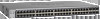
• GS728TPS Front-Panel and Back-Panel Configuration • GS752TS Front-Panel and Back-Panel Configuration • GS752TPS Front-Panel and Back-Panel Configuration • LED Designations • Device Hardware Interfaces GS728TS Front-Panel and Back-Panel Configuration The GS728TS Smart Switch has 24 10/100/1000 Mbps - Netgear GS752TS | GS7xxTS-TPS Hardware Installation Guide - Page 13
GS728TS, GS728TPS, GS752TS, and GS752TPS Smart Switch Hardware Installation Guide The front panel contains the following: • 24 RJ-45 connectors for 10/100/1000 Mbps autosensing Gigabit Ethernet switching ports. • 2 combo ports (port 23 and 24) to support 10/100/1000 Mbps copper or 100M/1G optical - Netgear GS752TS | GS7xxTS-TPS Hardware Installation Guide - Page 14
GS728TS, GS728TPS, GS752TS, and GS752TPS Smart Switch Hardware Installation Guide Power, Fan, LED mode, PoE Max, and Stack Master LEDs Stack ID LED Link/Speed/ACT LEDs Combo and Dedicated SFP Ports Factory Defaults Button Reset Button Select Button 10/100/1000M PoE capable Ethernet Ports - Netgear GS752TS | GS7xxTS-TPS Hardware Installation Guide - Page 15
, GS752TS, and GS752TPS Smart Switch Hardware Installation Guide GS752TS Front-Panel and Back-Panel Configuration The GS752TS Smart Switch has 48 10/100/1000 Mbps copper ports and 6 SFP fiber ports, 2 of which are combo ports. Up to two SFP ports (port 51 and 52) at a time can be used as stacking - Netgear GS752TS | GS7xxTS-TPS Hardware Installation Guide - Page 16
GS752TPS Smart Switch Hardware Installation Guide GS752TPS Front-Panel and Back-Panel Configuration The GS752TPS Smart Switch has 48 10/100/1000 Mbps PoE capable copper ports and 6 SFP fiber ports, 2 of which are combo ports. Up to two SFP ports (port 51 and 52) at a time can be used as stacking - Netgear GS752TS | GS7xxTS-TPS Hardware Installation Guide - Page 17
GS728TS, GS728TPS, GS752TS, and GS752TPS Smart Switch Hardware Installation Guide Figure 9. GS752TPS Back Panel The back panel contains a power connector. LED Designations Power Connector RJ-45 Port LEDs The following table describes the RJ-45 port LED - Netgear GS752TS | GS7xxTS-TPS Hardware Installation Guide - Page 18
GS728TS, GS728TPS, GS752TS, and GS752TPS Smart Switch Hardware Installation Guide SFP Port LEDs The OFF status. System LEDs The following table describes the system LED designations. LED Power Fan Stack Master LED Stack ID Designation • Solid Green - Device is powered on, run-time code is up and - Netgear GS752TS | GS7xxTS-TPS Hardware Installation Guide - Page 19
GS728TS, GS728TPS, GS752TS, and GS752TPS Smart Switch Hardware Installation Guide LED Max PoE LED LED Mode LED or an "uplink" connection (such as when connecting the port to a router, switch, or hub). • Configures the RJ-45 port to enable communications with the attached device, without requiring - Netgear GS752TS | GS7xxTS-TPS Hardware Installation Guide - Page 20
all settings including the password, VLAN settings, and port configurations are removed. To operate the Factory Defaults button, insert a device such as a paper clip into the opening to press the recessed button for over two seconds. Select Button The Smart Switch GS728TP and GS752TP have a LED Mode - Netgear GS752TS | GS7xxTS-TPS Hardware Installation Guide - Page 21
GS728TS, GS728TPS, GS752TS, and GS752TPS Smart Switch Hardware Installation Guide Chapter 2. Physical Description | 21 - Netgear GS752TS | GS7xxTS-TPS Hardware Installation Guide - Page 22
GS728TS, GS728TPS, GS752TS, and GS752TPS Smart Switch is designed to provide flexibility in configuring your network connections. It can be used as your only network traffic-distribution device or with 10 Mbps, 100 Mbps, and 1000 Mbps hubs and switches. Desktop Switching The Smart Switch can be used - Netgear GS752TS | GS7xxTS-TPS Hardware Installation Guide - Page 23
, GS752TS, and GS752TPS Smart Switch Hardware Installation Guide Backbone Switching You can use the GS728TS, GS728TPS, GS752TS, and GS752TPS Smart Switch as a backbone switch in a small network that gives users high-speed access to servers and other network devices. GS752TS Power Fan Stack - Netgear GS752TS | GS7xxTS-TPS Hardware Installation Guide - Page 24
4 This chapter describes the installation procedures for your GS728TS, GS728TPS, GS752TS, and GS752TPS Smart Switch. Switch installation involves the following steps: Step 1: Preparing the Site Step 2: Installing the Switch Step 3: Checking the Installation Step 4: Connecting Devices to the - Netgear GS752TS | GS7xxTS-TPS Hardware Installation Guide - Page 25
GS728TS, GS728TPS, GS752TS, and GS752TPS Smart Switch Hardware Installation Guide Step 1: Preparing the Site Before you install the switch, ensure the operating environment meets the site requirements in the following table. Characteristics Requirements Mounting • Desktop installations - - Netgear GS752TS | GS7xxTS-TPS Hardware Installation Guide - Page 26
GS728TS, GS728TPS, GS752TS, and GS752TPS Smart Switch Hardware Installation Guide 4. Align the mounting holes in the brackets with the holes in the rack, and insert two pan-head screws with nylon washers through each bracket - Netgear GS752TS | GS7xxTS-TPS Hardware Installation Guide - Page 27
, GS728TPS, GS752TS, and GS752TPS Smart Switch Hardware Installation Guide Power Fan Stack Master ID GS752TXS 51F 52F SFP + Reset Factory Defaults Green=10G Link Yellow=1G Blink=ACT ` ` Figure 13. Connecting Devices to the Switch Connect each PC to an RJ-45 network port on the Switch - Netgear GS752TS | GS7xxTS-TPS Hardware Installation Guide - Page 28
GS752TS, and GS752TPS Smart Switch Hardware Installation Guide Figure 14. Installing and SFP Transceiver Module (GS752TPS Shown) Step 6: Installing Device as Stand-alone or Stack assume the stack-master role ("Switchover"). In the default configuration, the master and backup switches are assigned - Netgear GS752TS | GS7xxTS-TPS Hardware Installation Guide - Page 29
, GS752TS, and GS752TPS Smart Switch Hardware Installation Guide Figure 15. Stacking Topologies The device is "Plug and Play" in terms of stacking configuration. Before powering up the device, connect the devices into the required stacking topology. Then power up the devices. By default, the switch - Netgear GS752TS | GS7xxTS-TPS Hardware Installation Guide - Page 30
the first time, the Smart Switch can be configured using a Web browser or a program called Smart Control Center. For more information about managing the switch, see the Software Administration Manual on the Smart Switch Resource CD. Note: The switch is configured with a default IP address of 192.168 - Netgear GS752TS | GS7xxTS-TPS Hardware Installation Guide - Page 31
chapter provides information about troubleshooting the NETGEAR Smart Switch. Topics include the following: • Troubleshooting Chart • Additional Troubleshooting Suggestions Troubleshooting Chart The following table lists symptoms, causes, and solutions of possible problems. Symptom Cause Solution - Netgear GS752TS | GS7xxTS-TPS Hardware Installation Guide - Page 32
unit from the stack. Use the Web Management to configure the unit as a stackable unit, with last two ports used as the stacking ports. Refer to the Smart Switch Software Administration Manual for information about using the Web interface. Additional Troubleshooting Suggestions If the suggestions - Netgear GS752TS | GS7xxTS-TPS Hardware Installation Guide - Page 33
MDI) IEEE802.3at (DTE Power via MDI Enhancements) Management Windows 2000 + XP, Vista; Windows 7, Microsoft Explorer 7.0 or above IEEE 802.1Q VLAN IEEE 802.3ad Link Aggregation IEEE 802.1D Spanning ) IGMP Snooping v1/v2/v3 IEEE 802.1p Class of Service (CoS) Appendix : Technical Specifications | 33 - Netgear GS752TS | GS7xxTS-TPS Hardware Installation Guide - Page 34
GS728TS, GS728TPS, GS752TS, and GS752TPS Smart Switch Hardware Installation Guide SNTP (Simple Network Time Protocol) 3 servers. Disabled by default. Jumbo Frame Support (9K) IPv6 Management, Multicast, and QoS Static Routing MLD Snooping DHCP Snooping Protocol and MAC based VLAN DoS and Auto DoS - Netgear GS752TS | GS7xxTS-TPS Hardware Installation Guide - Page 35
, GS752TS, and GS752TPS Smart Switch Hardware Installation Guide Performance Specifications Forwarding modes: Store-and-forward Bandwidth (per unit): 56 Gbps for GS728TS/TPS, 104 Gbps for GS752TS/TPS Stacking up to 6 switches Address database size: 16K media access control (MAC) addresses per - Netgear GS752TS | GS7xxTS-TPS Hardware Installation Guide - Page 36
, GS728TPS, GS752TS, and GS752TPS Smart Switch Hardware Installation Guide • Amperage (max): 1.4A GS728TS • AC Voltage: 100-240 V • Frequency: 50-60 Hz • Amperage (max): 1.4A Physical Specifications Dimensions (H x W x D): • GS752TPS 440 x 310 x 43 mm • GS728TPS 440 x 257 x 43 mm • GS752TS 440 x 257 - Netgear GS752TS | GS7xxTS-TPS Hardware Installation Guide - Page 37
GS728TS, GS728TPS, GS752TS, and GS752TPS Smart Switch Hardware Installation Guide CCC Appendix : Technical Specifications | 37 - Netgear GS752TS | GS7xxTS-TPS Hardware Installation Guide - Page 38
GS728TS, GS728TPS, GS752TS, and GS752TPS Smart Switch Hardware Installation Guide 38 | Appendix : Technical Specifications - Netgear GS752TS | GS7xxTS-TPS Hardware Installation Guide - Page 39
with any other antenna or transmitter. FCC Declaration Of Conformity We, NETGEAR, Inc., 350 East Plumeria Drive, San Jose, CA 95134, declare under our sole responsibility that the GS728TS, GS728TPS, GS752TS, and GS752TPS Smart Switch complies with Part 15 of FCC Rules. Operation is subject to the - Netgear GS752TS | GS7xxTS-TPS Hardware Installation Guide - Page 40
GS728TS, GS728TPS, GS752TS, and GS752TPS Smart Switch Hardware Installation Guide • This device must accept any interference received, including interference that may cause undesired operation. FCC Radio Frequency Interference Warnings & Instructions This equipment has been tested and found to - Netgear GS752TS | GS7xxTS-TPS Hardware Installation Guide - Page 41
Unshielded Twisted-Pair 7 Checking the Installation 26 Class of Service 7 compliance 39 Connecting Devices to the Switch 26, 27 Crossover 19 D Default Reset Button 13, 14, 15, 16 Device Hardware Select Button 14, 16, 20 SFP ports 19 LEDs 18 Smart Switch Resource CD 11 Straight-through 19 Index | 41 - Netgear GS752TS | GS7xxTS-TPS Hardware Installation Guide - Page 42
GS728TS, GS728TPS, GS752TS, and GS752TPS Smart Switch Hardware Installation Guide System LEDs 18 T technical support 2 Temperature 25 trademarks 2 Traffic Control 7 Troubleshooting Chart 31 U User Intervention 19 User's Manual 11 UTP 27 V Ventilation 25 VLAN 7 W Web-based Graphical User Interface 7
-
 1
1 -
 2
2 -
 3
3 -
 4
4 -
 5
5 -
 6
6 -
 7
7 -
8
-
9
-
10
-
11
-
12
-
13
-
14
-
15
-
16
-
17
-
18
-
19
-
20
-
21
-
22
-
23
-
24
-
25
-
26
-
27
-
28
-
29
-
30
-
31
-
32
-
33
-
34
-
35
-
36
-
37
-
38
-
39
-
40
-
41
-
42
 |
 |

350 East Plumeria Drive
San Jose, CA 95134
USA
January 2012
202-10994-01
v1.0
GS728TS, GS728TPS,
GS752TS, and GS752TPS
Smart Switch
Hardware Installation Guide