Netgear GS752TS GS7xxTS-TPS Hardware Installation Guide - Page 28
Step 6: Installing Device as Stand-alone or Stack Master
 |
View all Netgear GS752TS manuals
Add to My Manuals
Save this manual to your list of manuals |
Page 28 highlights
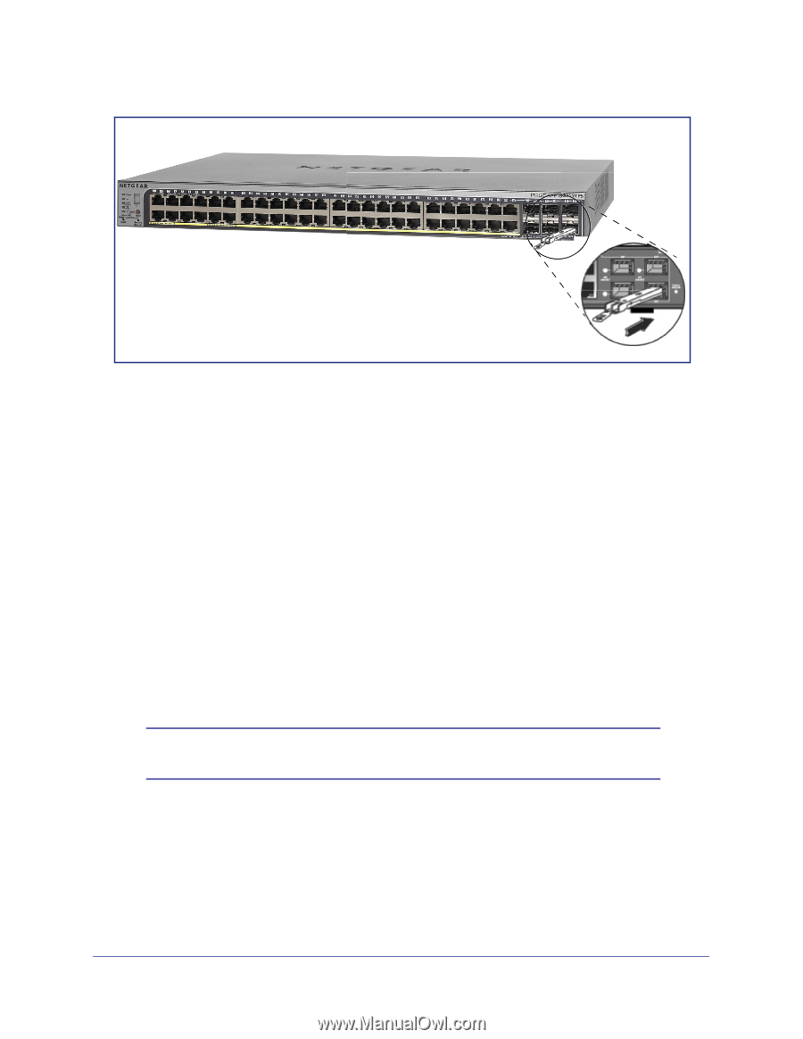
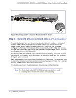
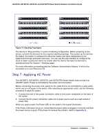
GS728TS, GS728TPS, GS752TS, and GS752TPS Smart Switch Hardware Installation Guide Figure 14. Installing and SFP Transceiver Module (GS752TPS Shown) Step 6: Installing Device as Stand-alone or Stack Master A master-backup unit runs as a slave unit as described above. In addition, it continuously monitors the existence and operation of the stack master. If the master unit fails, the master-backup unit will assume the stack-master role ("Switchover"). In the default configuration, the master and backup switches are assigned unit ID 1 and 2, respectively; however, the administrator may use the Web interface to assign different unit IDs. The time cost for switchover is under 30 seconds. If a stacking cable fails or a stack unit is extracted in a chain topology, slave units could be disconnected from the stack (which puts them in an ambiguous state), and they will set all their ports to the down state. Each unit may work in one of two modes: Stand-alone, or Stack mode. The operational mode is determined at software boot time, and can only be changed by a unit reset. The 7-segment stacking ID LED remains illuminated in both modes. The device supports two stacking topologies: Ring topology or Chain topology. Note: The direct attach cable AGC761 (2.5G) is recommended to be used as a stacking cable. The AGC761 cable is sold separately. 28 | Chapter 4. Installation
-
 1
1 -
2
-
3
-
4
-
5
-
6
-
7
-
8
-
9
-
10
-
11
-
12
-
13
-
14
-
15
-
16
-
17
-
18
-
19
-
20
-
21
-
22
-
 23
23 -
 24
24 -
 25
25 -
 26
26 -
 27
27 -
 28
28 -
 29
29 -
 30
30 -
 31
31 -
 32
32 -
 33
33 -
34
-
35
-
36
-
37
-
38
-
39
-
40
-
41
-
42
 |
 |