Netgear GS752TS GS7xxTS-TPS Hardware Installation Guide - Page 29
Step 7: Applying AC Power, Appendix
 |
View all Netgear GS752TS manuals
Add to My Manuals
Save this manual to your list of manuals |
Page 29 highlights
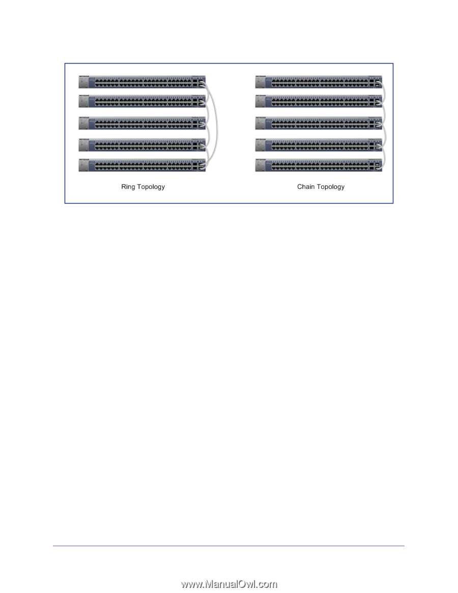
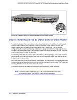
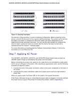
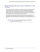
GS728TS, GS728TPS, GS752TS, and GS752TPS Smart Switch Hardware Installation Guide Figure 15. Stacking Topologies The device is "Plug and Play" in terms of stacking configuration. Before powering up the device, connect the devices into the required stacking topology. Then power up the devices. By default, the switch is configured to allow the master and slave designations to be determined through automatic discovery. You can use the web interface to configure the stack to select a particular switch as master after the device has been booted and is operational (see the System > Stacking page). For more information on stacking see the Software Administration Manual. A link to this document is on your Resource CD. Step 7: Applying AC Power The GS728TS, GS728TPS, GS752TS, and GS752TPS Smart Switch does not have an ON/OFF switch. Power is controlled by the power cord connection. Before connecting the power cord, select an AC outlet that is not controlled by a wall switch, which can turn off power to the switch. After selecting an appropriate outlet, use the following procedure to apply AC power: 1. Connect the end of the power connection cable to the power receptacle on the back of the switch. 2. Connect the AC power connection cable into a power source such as a wall socket or power strip. When you apply power, the Power LED on the switch's front panel illuminates. If the Power LED does not go on, check that the power cable is plugged in correctly and that the power source is good. If this does not resolve the problem, refer to Appendix A. Chapter 4. Installation | 29
-
 1
1 -
2
-
3
-
4
-
5
-
6
-
7
-
8
-
9
-
10
-
11
-
12
-
13
-
14
-
15
-
16
-
17
-
18
-
19
-
20
-
21
-
22
-
23
-
 24
24 -
 25
25 -
 26
26 -
 27
27 -
 28
28 -
 29
29 -
 30
30 -
 31
31 -
 32
32 -
 33
33 -
 34
34 -
35
-
36
-
37
-
38
-
39
-
40
-
41
-
42
 |
 |