Netgear GS752TS GS7xxTS-TPS Hardware Installation Guide - Page 25
Step 1: Preparing the Site, Step 2: Installing the Switch, Installing the Switch on a Flat Surface
 |
View all Netgear GS752TS manuals
Add to My Manuals
Save this manual to your list of manuals |
Page 25 highlights
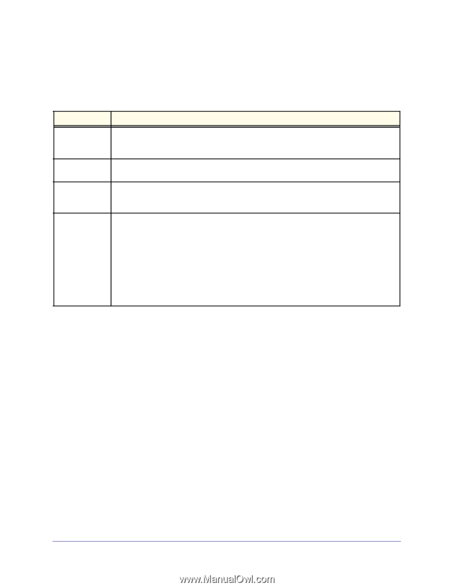
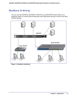
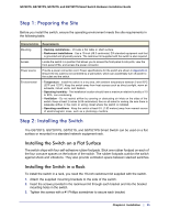
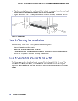
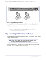
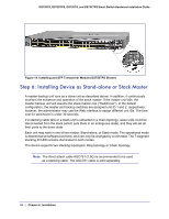
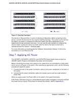
GS728TS, GS728TPS, GS752TS, and GS752TPS Smart Switch Hardware Installation Guide Step 1: Preparing the Site Before you install the switch, ensure the operating environment meets the site requirements in the following table. Characteristics Requirements Mounting • Desktop installations - Provide a flat table or shelf surface. • Rackmount installations - Use a 19-inch (48.3-centimeter) EIA standard equipment rack that is grounded and physically secure. The rackmount kit supplied with the switch is also required. Access Locate the switch in a position that allows you to access the front-panel RJ-45 ports, view the front-panel LEDs, and access the power connector. Power source Provide a power connection cord. Power specifications for the switch are shown in Appendix A. Ensure the AC outlet is not controlled by a wall switch, which can accidentally turn off power to the outlet and the switch. Environmental • Temperature - Install the switch in a dry area, with ambient temperature between 0 and 50ºC (32ºF and 122ºF). Keep the switch away from heat sources such as direct sunlight, warm air exhausts, hot-air vents, and heaters. • Operating humidity - The installation location should have a maximum relative humidity of 10 to 90%, non-condensing. • Ventilation - Do not restrict airflow by covering or obstructing air inlets on the sides of the switch. Keep at least 2 inches (5.08 centimeters) free on all sides for cooling. Be sure there is adequate airflow in the room or wiring closet where the switch is installed. • Operating conditions - Keep the switch at least 6 ft. (1.83 meters) away from nearest source of electromagnetic noise, such as a photocopy machine. Step 2: Installing the Switch The GS728TS, GS728TPS, GS752TS, and GS752TPS Smart Switch can be used on a flat surface or mounted in a standard network equipment rack. Installing the Switch on a Flat Surface The switch ships with four self-adhesive rubber footpads. Stick one rubber footpad on each of the four concave spaces on the bottom of the switch. The rubber footpads cushion the switch against shock and vibrations. They also provide ventilation space between stacked switches. Installing the Switch in a Rack To install the switch in a rack, you need the 19-inch rackmount kit supplied with the switch. 1. Attach the supplied mounting brackets to the side of the switch. 2. Insert the screws provided in the rackmount kit through each bracket and into the bracket mounting holes in the switch. 3. Tighten the screws with a #1 Phillips screwdriver to secure each bracket. Chapter 4. Installation | 25
-
 1
1 -
2
-
3
-
4
-
5
-
6
-
7
-
8
-
9
-
10
-
11
-
12
-
13
-
14
-
15
-
16
-
17
-
18
-
19
-
 20
20 -
 21
21 -
 22
22 -
 23
23 -
 24
24 -
 25
25 -
 26
26 -
 27
27 -
 28
28 -
 29
29 -
 30
30 -
31
-
32
-
33
-
34
-
35
-
36
-
37
-
38
-
39
-
40
-
41
-
42
 |
 |