Netgear GS752TS GS7xxTS-TPS Hardware Installation Guide - Page 19
Device Hardware Interfaces, RJ-45 Ports, SFP Ports
 |
View all Netgear GS752TS manuals
Add to My Manuals
Save this manual to your list of manuals |
Page 19 highlights
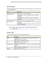
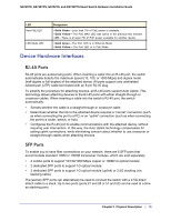
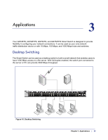
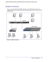
GS728TS, GS728TPS, GS752TS, and GS752TPS Smart Switch Hardware Installation Guide LED Max PoE LED LED Mode LED Designation • Solid Green -Less than 7W of PoE power is available. • Solid Yellow - The PoE MAX LED was active in the previous two minutes. • Off - There is at least 7W of PoE power available for another device. • Solid Green -The Port LED is in Ethernet Mode • Solid Yellow - The Port LED is in PoE Mode. Device Hardware Interfaces RJ-45 Ports RJ-45 ports are autosensing ports. When inserting a cable into an RJ-45 port, the switch automatically detects the maximum speed (10, 100, or 1000 Mbps) and duplex mode (half-duplex or full-duplex) of the attached device. All ports support only unshielded twisted-pair (UTP) cable terminated with an 8-pin RJ-45 plug. To simplify the procedure for attaching devices, all RJ-45 ports support Auto Uplink. This technology allows attaching devices to the RJ-45 ports with either straight-through or crossover cables. When inserting a cable into the switch's RJ-45 port, the switch automatically: • Senses whether the cable is a straight-through or crossover cable. • Determines whether the link to the attached device requires a "normal" connection (such as when connecting the port to a PC) or an "uplink" connection (such as when connecting the port to a router, switch, or hub). • Configures the RJ-45 port to enable communications with the attached device, without requiring user intervention. In this way, the Auto Uplink technology compensates for setting uplink connections, while eliminating concern about whether to use crossover or straight-through cables when attaching devices. SFP Ports To enable you to have fiber connections on your network, there are 6 SFP ports that accommodate standard 100M or 1000M transceiver modules, which are sold separately. • 2 combo ports to support 10/100/1000 Mbps copper or 100M/1G optical module. • 2 dedicated SFP ports to support 1G optical module. • 2 dedicated SFP ports to support 1G optical module (uplink) or 2.5G stacking (via stacking cable). The last two SFP ports can alternatively be used to connect the switch with a 2.5G direct attach cable to a stack. Up to two ports (ports 27 and 28 or 51 and 52) can be used at a time as stacking ports. Chapter 2. Physical Description | 19
-
 1
1 -
2
-
3
-
4
-
5
-
6
-
7
-
8
-
9
-
10
-
11
-
12
-
13
-
 14
14 -
 15
15 -
 16
16 -
 17
17 -
 18
18 -
 19
19 -
 20
20 -
 21
21 -
 22
22 -
 23
23 -
 24
24 -
25
-
26
-
27
-
28
-
29
-
30
-
31
-
32
-
33
-
34
-
35
-
36
-
37
-
38
-
39
-
40
-
41
-
42
 |
 |