Netgear GS752TS GS7xxTS-TPS Hardware Installation Guide - Page 26
Step 3: Checking the Installation, Step 4: Connecting Devices to the Switch, GS728TS
 |
View all Netgear GS752TS manuals
Add to My Manuals
Save this manual to your list of manuals |
Page 26 highlights
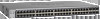
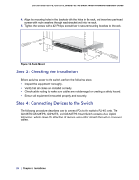
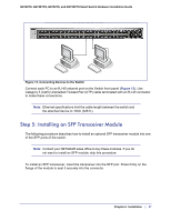
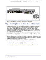
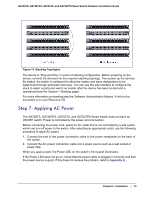
GS728TS, GS728TPS, GS752TS, and GS752TPS Smart Switch Hardware Installation Guide 4. Align the mounting holes in the brackets with the holes in the rack, and insert two pan-head screws with nylon washers through each bracket and into the rack. 5. Tighten the screws with a #2 Phillips screwdriver to secure mounting brackets to the rack. Power Fan Stack Master Reset Link/Act Mode YGerlleoewn==LLiinnkk at at 1G 10/ - 1 2 3 4 5 6 ID 100M 78 9 10 11 12 DFeafcatuolrtys 13 14 15 16 17 18 19 20 21 22 23 24 25 26 27 28 29 30 31 32 33 34 35 36 37 38 39 40 41 42 43 44 45 46 47 48 49F 50F 51F 52F SFP + Green=10BGliLnikn=kAYCeTllow=1G Figure 12. Rack Mount Step 3: Checking the Installation Before applying power to the switch, perform the following steps: • Inspect the equipment thoroughly. • Verify that all cables are installed correctly. • Check cable routing to make sure cables are not damaged or creating a safety hazard. • Ensure all equipment is mounted properly and securely. Step 4: Connecting Devices to the Switch The following procedure describes how to connect PCs to the switch's RJ-45 ports. The GS728TS, GS728TPS, GS752TS, and GS752TPS Smart Switch contains Auto Uplink technology, which allows the attaching of devices using either straight-through or crossover cables. 26 | Chapter 4. Installation
-
 1
1 -
2
-
3
-
4
-
5
-
6
-
7
-
8
-
9
-
10
-
11
-
12
-
13
-
14
-
15
-
16
-
17
-
18
-
19
-
20
-
 21
21 -
 22
22 -
 23
23 -
 24
24 -
 25
25 -
 26
26 -
 27
27 -
 28
28 -
 29
29 -
 30
30 -
 31
31 -
32
-
33
-
34
-
35
-
36
-
37
-
38
-
39
-
40
-
41
-
42
 |
 |
