Netgear GS752TS GS7xxTS-TPS Hardware Installation Guide - Page 27
Step 5: Installing an SFP Transceiver Module, Connecting Devices to the Switch
 |
View all Netgear GS752TS manuals
Add to My Manuals
Save this manual to your list of manuals |
Page 27 highlights
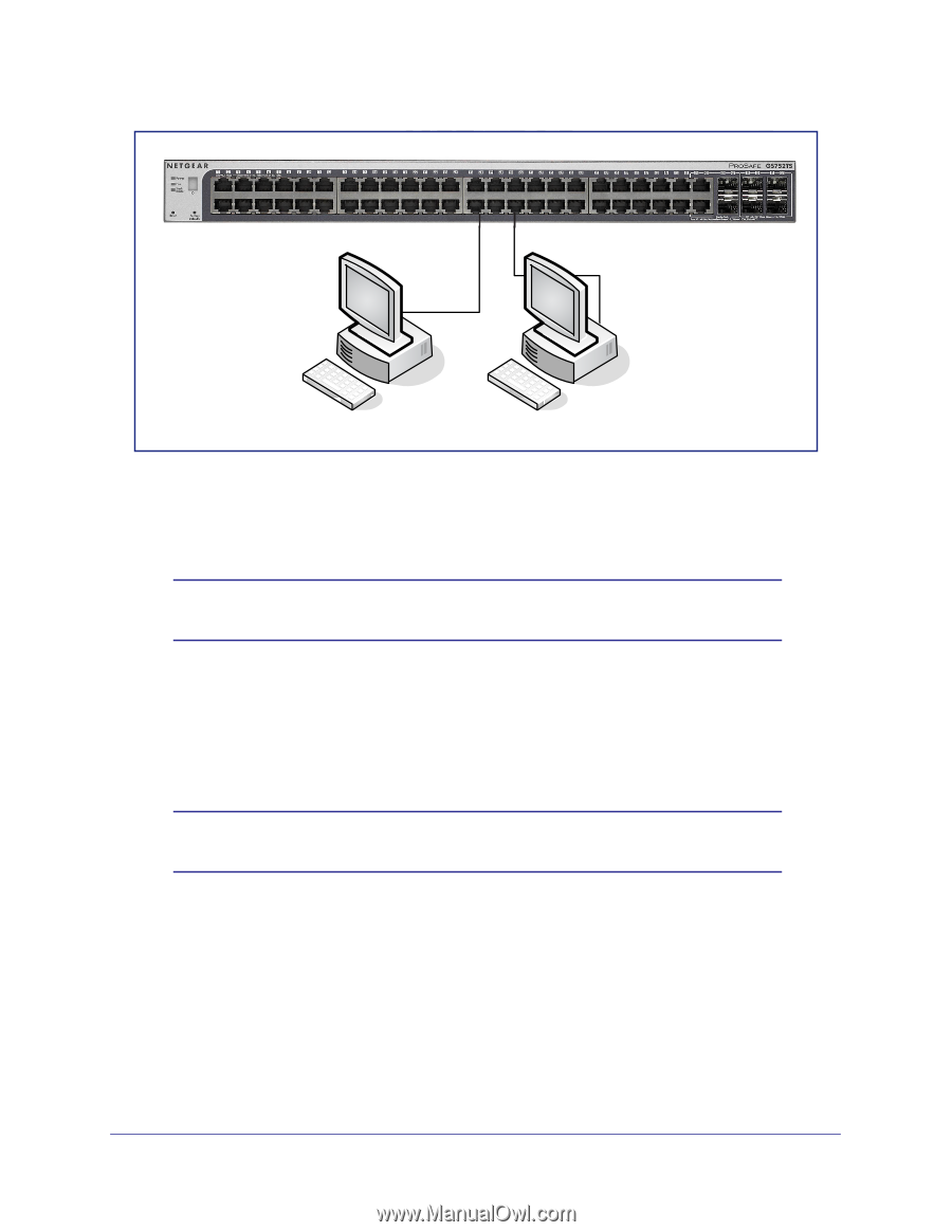
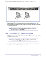
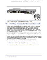
GS728TS, GS728TPS, GS752TS, and GS752TPS Smart Switch Hardware Installation Guide Power Fan Stack Master ID Link/Act Mode - 1 2 3 4 5 6 7 8 9 10 11 12 Green=Link at 1G Yellow=Link at 10/ 100M 13 14 15 16 17 18 19 20 21 22 23 24 25 26 27 28 29 30 31 32 33 34 35 36 37 38 39 40 41 42 43 44 45 46 47 48 49F 50F GS752TXS 51F 52F SFP + Reset Factory Defaults Green=10G Link Yellow=1G Blink=ACT ` ` Figure 13. Connecting Devices to the Switch Connect each PC to an RJ-45 network port on the Switch front panel (Figure 13). Use Category 5 (Cat5) Unshielded Twisted-Pair (UTP) cable terminated with an RJ-45 connector to make these connections. Note: Ethernet specifications limit the cable length between the switch and the attached device to 100m (328 ft.). Step 5: Installing an SFP Transceiver Module The following procedure describes how to install an optional SFP transceiver module into one of the SFP ports of the switch. Note: Contact your NETGEAR sales office to buy these modules. If you do not want to install an SFP module, skip this procedure. To install an SFP transceiver, insert the transceiver into the SFP port. Press firmly on the flange of the module to seat it securely into the connector. Chapter 4. Installation | 27
-
 1
1 -
2
-
3
-
4
-
5
-
6
-
7
-
8
-
9
-
10
-
11
-
12
-
13
-
14
-
15
-
16
-
17
-
18
-
19
-
20
-
21
-
 22
22 -
 23
23 -
 24
24 -
 25
25 -
 26
26 -
 27
27 -
 28
28 -
 29
29 -
 30
30 -
 31
31 -
 32
32 -
33
-
34
-
35
-
36
-
37
-
38
-
39
-
40
-
41
-
42
 |
 |