Nokia IP2255 Installation Guide
Nokia IP2255 - Security Appliance Manual
 |
View all Nokia IP2255 manuals
Add to My Manuals
Save this manual to your list of manuals |
Nokia IP2255 manual content summary:
- Nokia IP2255 | Installation Guide - Page 1
Nokia IP2255 Security Platform Installation Guide Part No. N450000275 Rev 002 Published March 2007 - Nokia IP2255 | Installation Guide - Page 2
to, procurement of substitute goods or services; loss of use, data, or Nokia is a registered trademark of Nokia Corporation. Other products mentioned in this document are trademarks or registered trademarks of their respective holders. 070101 2 Nokia IP2255 Security Platform Installation Guide - Nokia IP2255 | Installation Guide - Page 3
Americas Voice: Fax: Asia-Pacific Voice: Fax: https://support.nokia.com/ [email protected] Europe 1-888-361-5030 or 1-613-271-6721 Voice: 1-613-271-8782 Fax: +65-67232999 +65-67232897 +44 (0) 125-286-8900 +44 (0) 125-286-5666 050602 Nokia IP2255 Security Platform Installation Guide 3 - Nokia IP2255 | Installation Guide - Page 4
4 Nokia IP2255 Security Platform Installation Guide - Nokia IP2255 | Installation Guide - Page 5
Fan Unit 30 Storage Devices 31 Power Supplies 31 Product Disposal 32 Site Requirements, Warnings, and Cautions 33 Software Requirements 34 2 Installing Nokia IP2255 Appliances 37 Rack Mounting the Security Platform 37 Before You Begin 38 Nokia IP2255 Security Platform Installation Guide 5 - Nokia IP2255 | Installation Guide - Page 6
. . . 70 5 Installing, Replacing, and Configuring the Nokia Encryption Accelerator Card 73 Removing, Installing, and Replacing the Nokia Encryption Accelerator Card 74 Before you Begin 74 Configuring and Activating Encryption Acceleration 78 6 Nokia IP2255 Security Platform Installation Guide - Nokia IP2255 | Installation Guide - Page 7
100 8 Troubleshooting 105 General Troubleshooting Information 105 A Technical Specifications 113 Space Requirements 113 B Compliance Information 115 Declaration of Conformity 115 Compliance Statements 117 FCC Notice (US 118 Index 121 Nokia IP2255 Security Platform Installation Guide 7 - Nokia IP2255 | Installation Guide - Page 8
8 Nokia IP2255 Security Platform Installation Guide - Nokia IP2255 | Installation Guide - Page 9
Tables Table 1 Text Conventions 15 Table 2 NICs Available for the Network Interface Card Slots . . . 25 Table 3 System Status LEDs 29 Table 4 Power Supply Status LEDs 32 Nokia IP2255 Security Platform Installation Guide 9 - Nokia IP2255 | Installation Guide - Page 10
10 Nokia IP2255 Security Platform Installation Guide - Nokia IP2255 | Installation Guide - Page 11
Location Rear View 23 Figure 3 Ethernet Management Port Details 24 Figure 4 Slot Numbers for Network Interface Cards 25 Figure 5 Pin Assignments for Console Connection 27 Figure Fiber-Optic Gigabit Ethernet NIC Front Panel Details 67 Nokia IP2255 Security Platform Installation Guide 11 - Nokia IP2255 | Installation Guide - Page 12
Figure 20 Four-Port Fiber-Optic Gigabit Ethernet NIC Front Panel Details 68 Figure 21 ADP Single-Port 10 Gigabit Ethernet NIC 70 Figure 22 Location of Compact-Flash Memory Card 87 Figure 23 DIMM Socket Locations 92 12 Nokia IP2255 Security Platform Installation Guide - Nokia IP2255 | Installation Guide - Page 13
About this Guide This manual is written for network administrators. It provides information for the installation and use of the Nokia IP2255 Security Platform. Installation and maintenance should be performed by experienced technicians or Nokia-approved service providers only. This preface provides - Nokia IP2255 | Installation Guide - Page 14
how to install or replace the compact-flash memory card, DIMMs, the fan tray unit, power supplies, and the Ethernet management ports. „ Chapter 8, "Troubleshooting" describes problems you might encounter and proposes solutions to these problems. „ Appendix A, "Technical Specifications" provides - Nokia IP2255 | Installation Guide - Page 15
performance, loss of data, or interruption of service. Note Notes provide information of special interest or recommendations. Text Conventions Table 1 describes the text conventions this guide by a greater than sign (>): Choose File > Open. Nokia IP2255 Security Platform Installation Guide 15 - Nokia IP2255 | Installation Guide - Page 16
the Nokia IPSO boot manager „ Clustering Configuration Guide for the version of Nokia IPSO you are using „ Nokia Network Voyager inline help You can find the most up-to date version of the Nokia IP2255 Security Platform Installation Guide in PDF on the Nokia support site (https:// 16 Nokia IP2255 - Nokia IP2255 | Installation Guide - Page 17
support.nokia.com). You can access inline help, the Nokia Network Voyager Reference Guide, and the CLI Reference Guide from Nokia Network Voyager. Check Point documentation is available from the Check Point Web site at: http://www.checkpoint.com/ Nokia IP2255 Security Platform Installation Guide - Nokia IP2255 | Installation Guide - Page 18
18 Nokia IP2255 Security Platform Installation Guide - Nokia IP2255 | Installation Guide - Page 19
performance when running Check Point VPN-1 enterprise applications. The ADP technology also allows the Nokia operating system and Check Point VPN-1 enterprise applications to accelerate other data link, network, and transport layer functions. Nokia IP2255 Security Platform Installation Guide - Nokia IP2255 | Installation Guide - Page 20
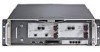
Nokia IP2255 appliances support an encryption accelerator card to further enhance VPN performance. Nokia IP2255 is a three-rack unit (3U) appliance that incorporates a serviceable slide-out tray into the chassis design. Nokia IP2255 " on page 55. 20 Nokia IP2255 Security Platform Installation Guide - Nokia IP2255 | Installation Guide - Page 21
management ports „ Four network interface card (NIC) slots, controlled by two Nokia ADP subsystems „ Console port „ Serial (AUX) port for a modem connection „ Two PC-card slots that support compact-flash memory „ Fan tray unit with N + 1 cooling Nokia IP2255 Security Platform Installation Guide 21 - Nokia IP2255 | Installation Guide - Page 22
10/100/1000 Ethernet management ports The flash memory in the internal compact-flash slot provides the primary application and operating system storage. The power supplies are located at the back of the IP2255 appliance, as shown in Figure 2. 22 Nokia IP2255 Security Platform Installation Guide - Nokia IP2255 | Installation Guide - Page 23
management ports are not suitable for forwarding production data traffic. Do not use them for this purpose. Nokia recommends that you configure one port as the primary management interface and a second port as the backup management interface. Nokia IP2255 Security Platform Installation Guide 23 - Nokia IP2255 | Installation Guide - Page 24
performance. Nokia Network Interface Cards The Nokia IP2255 appliances have four network interface card (NIC) slots. Each slot can accommodate one NIC. The NICs interface with the ADP subsystem. Figure 4 shows the slot numbers for the NIC slots. 24 Nokia IP2255 Security Platform Installation - Nokia IP2255 | Installation Guide - Page 25
" on page 60 One-port fiber-optic 10 Gigabit Ethernet NIC "Fiber-Optic 10 Gigabit Ethernet NIC Features" on page 69 Nokia encryption accelerator card "Installing, Replacing, and Configuring the Nokia Encryption Accelerator Card" on page 73 Nokia IP2255 Security Platform Installation Guide 25 - Nokia IP2255 | Installation Guide - Page 26
in Figure 1 on page 22, to supply information that makes the appliance available on the network. Figure 5 provides pin assignment information for console connections. 26 Nokia IP2255 Security Platform Installation Guide - Nokia IP2255 | Installation Guide - Page 27
Nokia IP2255 Appliance Overview Figure 5 Pin Assignments for Console Connection 1 5 6 9 Pin Assignment Input/Output 1 DCD Input 2 connection to manage the appliance. Figure 6 provides pinassignment information for modem connections. Nokia IP2255 Security Platform Installation Guide 27 - Nokia IP2255 | Installation Guide - Page 28
) 3 (RXD) 20 (DTR) 7 (GND) 6 (DSR) 4 (RTS) 5 (CTS) 22 (RI) To DB9 cable out 7 (RTS) 8 (CTS) 3 (TXD) 2 (RXD 6 (DSR) 9 (RI) 5 (GND) 4 (DTR) 1 (DCD) 1 (DCD) 4 (DTR) 28 Nokia IP2255 Security Platform Installation Guide - Nokia IP2255 | Installation Guide - Page 29
Nokia IP2255 Appliance Overview System Status LEDs You can monitor the basic operation of the your appliance LEDs Status indicator Meaning Symbol Solid blue Power on Solid yellow Appliance is experiencing an internal voltage problem. ! Nokia IP2255 Security Platform Installation Guide 29 - Nokia IP2255 | Installation Guide - Page 30
is experiencing a problem. The location and meaning of the status LEDs for the installed NICs is described in Chapter 4, "Connecting to the Network Interface Cards." Fan Unit The Nokia IP2255 appliance fan , see "System Status LEDs" on page 29. 30 Nokia IP2255 Security Platform Installation Guide - Nokia IP2255 | Installation Guide - Page 31
Nokia IPSO images and configuration files Power Supplies The Nokia IP2255 appliance supports two power supplies for enhanced power sharing and redundancy. The power supplies are hot swappable and perform each power supply, as shown in Figure 8. Nokia IP2255 Security Platform Installation Guide 31 - Nokia IP2255 | Installation Guide - Page 32
Red Power supply has a voltage problem and power is turned off. OVR TEMP Yellow Power supply has an internal temperature problem. All power to the unit , Nokia encourages you to dispose of these devices in an environmentally-friendly manner. 32 Nokia IP2255 Security Platform Installation Guide - Nokia IP2255 | Installation Guide - Page 33
to the environmental specifications listed in Appendix A, "Technical Specifications." Warning Hazardous radiation exposure can occur if you use controls, make performance adjustments, or follow procedures that are not described in this document. Nokia IP2255 Security Platform Installation Guide 33 - Nokia IP2255 | Installation Guide - Page 34
of the following operating system and firewall software versions: Operating system requirements-Nokia IPSO v4.1 or later „ Firewall and VPN software requirements-Check Point VPN-1 versions compatible with the version of Nokia IPSO you are using. 34 Nokia IP2255 Security Platform Installation Guide - Nokia IP2255 | Installation Guide - Page 35
For information about updates to the software requirements or additional applications that have become available since this guide was published, contact your Nokia service provider, as listed in "Nokia Contact Information" on page 3. Nokia IP2255 Security Platform Installation Guide 35 - Nokia IP2255 | Installation Guide - Page 36
1 Overview 36 Nokia IP2255 Security Platform Installation Guide - Nokia IP2255 | Installation Guide - Page 37
2 Installing Nokia IP2255 Appliances This chapter describes how to install Nokia IP2255 appliances in a standard equipment rack. Caution To help guard against electrostatic discharge damage, make sure you are properly grounded by using a grounding wrist strap and following the instructions provided - Nokia IP2255 | Installation Guide - Page 38
tray assembly from the chassis before you install the security platform in the equipment rack. To rack mount the appliance, you need: „ A Phillips-head screwdriver „ Suitable, grounded work surface on which to place the chassis tray assembly 38 Nokia IP2255 Security Platform Installation Guide - Nokia IP2255 | Installation Guide - Page 39
100/1000BaseT 5 7 6 8 5 7 6 8 SLOT 5 1 3 57 L A L A 2 4 68 1 3 57 L A L A 2 4 68 1 2 3 4 IP2255 00010 Fan unit Retaining screws b. Loosen the retaining screws by turning them counterclockwise by hand or by using a screwdriver. Nokia IP2255 Security Platform Installation Guide 39 - Nokia IP2255 | Installation Guide - Page 40
2 Installing Nokia IP2255 Appliances c. Slowly pull the fan unit out of the chassis toward the front. 10Base-SR X2 SLOT 1 A 10Base-SR X2 TEMP PWR FAULT OVR OK TEMP 00034 b. Loosen the retaining screws by turning them counterclockwise. 40 Nokia IP2255 Security Platform Installation Guide - Nokia IP2255 | Installation Guide - Page 41
Rack Mounting the Security Platform c. Use the handle to gently pull each power supply out of the chassis. FAULT TOEVMRP POWKR FAULT TOEVMRP POWKR 00083 4. Optionally, remove the chassis tray assembly from the security platform. Nokia IP2255 Security Platform Installation Guide 41 - Nokia IP2255 | Installation Guide - Page 42
Installing Nokia IP2255 Appliances Caution To help guard against electrostatic discharge, follow the instructions 5 7 6 8 SLOT 5 1 3 57 L A L A 2 4 68 1 3 57 L A L A 2 4 68 1 2 3 4 Chassis tray assembly retaining screws IP2255 00010 42 Nokia IP2255 Security Platform Installation Guide - Nokia IP2255 | Installation Guide - Page 43
L A 7 L A 8 L A 5 7 1 2 3 4 IP2255 Chassis tray assembly release tab 00094 You must lift the right side of the chassis tray assembly slightly as you pull it out of the chassis so that the release tab clears the slot on the chassis. Nokia IP2255 Security Platform Installation Guide 43 - Nokia IP2255 | Installation Guide - Page 44
place and resecure the four chassis tray assembly retaining screws. 8. Reinstall the fan unit into the front of the appliance. 9. Reinstall the power supplies. 44 Nokia IP2255 Security Platform Installation Guide - Nokia IP2255 | Installation Guide - Page 45
the Command-Line Interface „ Using Nokia Horizon Manager For information about how to use the DHCP client for the initial configuration, see the Read Me First document, Using DHCP to Configure Your Appliance, included with the security platform. Nokia IP2255 Security Platform Installation Guide 45 - Nokia IP2255 | Installation Guide - Page 46
install the Nokia encryption accelerator card, see Chapter 5, "Installing, Replacing, and Configuring the Nokia Encryption Accelerator Card." Using a Console Connection If you do not use DHCP to perform the initial configuration of your Nokia . 46 Nokia IP2255 Security Platform Installation Guide - Nokia IP2255 | Installation Guide - Page 47
5 7 6 8 5 7 6 8 SLOT 5 1 3 57 L A L A 2 4 68 1 3 57 L A L A 2 4 68 1 2 3 4 IP2255 00010 For cable pin assignments for the console connection, see "Console Port" on page 26. 2. Connect the appliance as shown in Figure 10. Nokia IP2255 Security Platform Installation Guide 47 - Nokia IP2255 | Installation Guide - Page 48
Performing the Initial Configuration Figure 10 Power Switch Location (Rear View) Power cord receptacles PWR FAULT OVR OK TEMP Power switches PWR FAULT OVR OK TEMP 00034 Caution To avoid potential service provide power to the appliance. 48 Nokia IP2255 Security Platform Installation Guide - Nokia IP2255 | Installation Guide - Page 49
wall receptacle into which you plugged the appliance. If the fans are still not running, or if the power LED does not illuminate, contact your Nokia service provider as listed in "Nokia Contact Information" on page 3 for technical support. Nokia IP2255 Security Platform Installation Guide 49 - Nokia IP2255 | Installation Guide - Page 50
password, and to configure the management interface. To perform the initial configuration 1. Turn on the appliance. how to use the boot manager, see the Nokia IPSO Boot Manager Reference Guide. After some miscellaneous output appears, the following Nokia IP2255 Security Platform Installation Guide - Nokia IP2255 | Installation Guide - Page 51
select an interface, Nokia recommends that you select one of the Ethernet management ports, which are numbered eth-s5p1 through eth-s5p4. To select an interface, enter the number adjacent to the physical ID in the list of connected interfaces. Nokia IP2255 Security Platform Installation Guide 51 - Nokia IP2255 | Installation Guide - Page 52
3 Performing the Initial Configuration Note A physical ID identifies the network interface card type (eth) and provides information about its slot number (slot-num) and port number (port-num). The Ethernet NIC Connectors and Cables" on page 68. 52 Nokia IP2255 Security Platform Installation Guide - Nokia IP2255 | Installation Guide - Page 53
how to use Network Voyager, see "Viewing Nokia IPSO Documentation by Using Nokia Network Voyager" later in this section. To open Nokia Network Voyager 1. Open a Web browser on password you entered when you performed the initial configuration. Nokia IP2255 Security Platform Installation Guide 53 - Nokia IP2255 | Installation Guide - Page 54
routing problem. Confirm the information you entered during the initial configuration and check that all cables are firmly connected. For more information, see the troubleshooting section in the installation guide for your appliance. Viewing Nokia IPSO Documentation by Using Nokia Network Voyager - Nokia IP2255 | Installation Guide - Page 55
help) Using the Command-Line Interface You can also use the IPSO command-line interface (CLI) to manage and configure Nokia appliances from the command line. Everything that you can accomplish with Network Voyager you can also do with the CLI. Nokia IP2255 Security Platform Installation Guide 55 - Nokia IP2255 | Installation Guide - Page 56
3 Performing the Initial Configuration To access the command-line interface 1. Log on to the appliance by using . For more information about how to access and use the CLI, see the Nokia CLI Reference Guide for the version of IPSO you are using. 56 Nokia IP2255 Security Platform Installation Guide - Nokia IP2255 | Installation Guide - Page 57
enterprise, managed service provider (MSP), or hosted applications service provider network (ASP). For information about how to obtain Horizon Manager or to learn more about the Horizon Manager, see "Nokia Contact Information" on page 3. 051115 Nokia IP2255 Security Platform Installation Guide 57 - Nokia IP2255 | Installation Guide - Page 58
3 Performing the Initial Configuration 58 Nokia IP2255 Security Platform Installation Guide - Nokia IP2255 | Installation Guide - Page 59
add or replace a NIC, see Chapter 6, "Installing and Replacing Network Interface Cards." For information about the Ethernet management ports in slot 5, see "Ethernet Management Ports" on page 23. The NICs that the Nokia IP2255 appliances support connect to the Nokia ADP subsystem. All NICs are hot - Nokia IP2255 | Installation Guide - Page 60
requirements applicable to this product, see "Software Requirements" on page 34. 10/100 Ethernet NIC Features The eight-port Ethernet NIC supports tracing through tcpdump. Figure 12 shows the front panel layout of the eight-port Ethernet NIC. 60 Nokia IP2255 Security Platform Installation Guide - Nokia IP2255 | Installation Guide - Page 61
Ethernet NIC Figure 12 Eight-Port Ethernet NIC Front Panel Details Odd-numbered ports (1, 3, 5, 7) 10/100BaseT 1 3 5 2 4 6 Even-numbered ports (2, 4, 6, 8) 7 1357 L A L A 8 shielded twisted-pair, full-duplex, or half-duplex cable. Nokia IP2255 Security Platform Installation Guide 61 - Nokia IP2255 | Installation Guide - Page 62
for the Ethernet Cable 8 1 Pin 1 00270 2 3 4 5 6 7 Assignme nt TX + TX RX + RX - Figure 14 shows the pin assignments for the RJ-45 crossover cable. 62 Nokia IP2255 Security Platform Installation Guide - Nokia IP2255 | Installation Guide - Page 63
in Figure 15. Figure 15 Gigabit Ethernet Crossover Cable Pin Connections 1 1 2 2 3 3 4 4 5 5 6 6 7 7 8 8 00020 You can order appropriate adapter cables separately from a cable vendor of your choice. Nokia IP2255 Security Platform Installation Guide 63 - Nokia IP2255 | Installation Guide - Page 64
Interface Cards Two-Port and Four-Port Copper Gigabit Ethernet NIC The Nokia IP2255 appliance supports Nokia-approved, two-port and four-port copper Gigabit Ethernet NICs. For LEDs (yellow) Transmit LEDs (yellow Link LEDs (green) 00292.1 64 Nokia IP2255 Security Platform Installation Guide - Nokia IP2255 | Installation Guide - Page 65
and transmitted (TX), the appropriate LEDs on the appliance illuminate (yellow). The IP2255 appliances can accommodate up to four copper Gigabit Ethernet NICs. Copper Gigabit Ethernet NIC twisted-pair, full-duplex, or half-duplex cable. Nokia IP2255 Security Platform Installation Guide 65 - Nokia IP2255 | Installation Guide - Page 66
Note For IP2255 appliances, Nokia recommends the use of shielded twistedpair cables and connectors for best Electromagnetic Interference and Immunity performance. For Cable Pin Connections 1 1 2 2 3 3 4 4 5 5 6 6 7 7 8 8 00020 66 Nokia IP2255 Security Platform Installation Guide - Nokia IP2255 | Installation Guide - Page 67
Ethernet NIC Two-Port and Four-Port Fiber-Optic Gigabit Ethernet NIC The Nokia IP2255 appliance supports Nokia-approved, two-port and four-port multimode fiber-optic Gigabit Ethernet NICs. layout of the four-port fiber-optic Gigabit Ethernet NIC. Nokia IP2255 Security Platform Installation Guide 67 - Nokia IP2255 | Installation Guide - Page 68
(RX) and transmitted (TX), the appropriate LEDs on the appliance illuminate (yellow). The IP2255 appliances can accommodate up to four fiber-optic Gigabit Ethernet NICs. Fiber-Optic Gigabit Ethernet with each two-port Gigabit Ethernet NIC. 68 Nokia IP2255 Security Platform Installation Guide - Nokia IP2255 | Installation Guide - Page 69
front panel details for the single-port fiber-optic 10 Gigabit Ethernet NIC you can use in Nokia IP2255 appliances. Note The NIC shown in the figure is the short range version; the LEDs are the same for both short-range and long-range versions. Nokia IP2255 Security Platform Installation Guide 69 - Nokia IP2255 | Installation Guide - Page 70
the connection. The link LEDs on the NIC illuminate after internal components initialize. The IP2255 appliances can accommodate up to two fiber-optic 10 Gigabit Ethernet NICs. Fiber-Optic 10 You can order additional 10GBASE-SR (for short-range 70 Nokia IP2255 Security Platform Installation Guide - Nokia IP2255 | Installation Guide - Page 71
from a cable vendor of your choice. Cables that connect to the 10 Gigabit Ethernet NIC must be IEEE 802.3 compliant to prevent potential data loss. Nokia IP2255 Security Platform Installation Guide 71 - Nokia IP2255 | Installation Guide - Page 72
4 Connecting to the Network Interface Cards 72 Nokia IP2255 Security Platform Installation Guide - Nokia IP2255 | Installation Guide - Page 73
the Nokia Encryption Accelerator Card The Nokia IP2255 appliance supports the Nokia encryption accelerator card in the Nokia accelerated data path (ADP) card format. The Nokia encryption accelerator card provides high-speed cryptographic processing that enhances performance. The Nokia encryption - Nokia IP2255 | Installation Guide - Page 74
and Replacing the Nokia Encryption Accelerator Card The Nokia IP2255 appliances have four slots on the front of the appliance that hold one NIC each. You can install the Nokia encryption accelerator card in any available slot. The Nokia encryption accelerator card does not support hot swapping. You - Nokia IP2255 | Installation Guide - Page 75
If no NIC is currently installed, remove the two retaining screws on the blank plate that covers the slot and proceed to step 8. 4. Press the red button on the ejector and locking lever on the encryption accelerator card. The lock is released. Nokia IP2255 Security Platform Installation Guide 75 - Nokia IP2255 | Installation Guide - Page 76
2 4 3 5 4 3 6 5 4 6 SLOT 5 7 1 L 3 A 5 7 8 L A 7 L A 8 L A 5 7 IP2255 1 2 3 4 00062 6. Continue to press or push the lever outward until the NIC is released and extends slightly beyond the front panel of the appliance. 76 Nokia IP2255 Security Platform Installation Guide - Nokia IP2255 | Installation Guide - Page 77
the reset button on the front panel of the security platform. If you used the CLI to halt the system, press any key to reboot. Nokia IP2255 Security Platform Installation Guide 77 - Nokia IP2255 | Installation Guide - Page 78
acceleration is registered with the Check Point software on your appliance. After you register the module, you must install the Check Point security policy on the firewall for the Nokia encryption accelerator card to perform IKE acceleration. 78 Nokia IP2255 Security Platform Installation Guide - Nokia IP2255 | Installation Guide - Page 79
and Replacing Network Interface Cards The Nokia IP2255 appliance supports network interface cards (NICs) in the Nokia accelerated data path (ADP) format. The Nokia IP2255 appliances come with the NICs you ordered already installed. You can hot swap the NICs in any of the four slots on the - Nokia IP2255 | Installation Guide - Page 80
are properly grounded before you touch any electronic component. Removing, Installing, and Replacing NICs The Nokia IP2255 appliances have four slots on the front of the appliance that hold one NIC each. Because the Nokia IP2255 appliances support hot swapping of NICs, you do not have to turn off - Nokia IP2255 | Installation Guide - Page 81
side of the NIC. Note If no NIC is currently installed, remove the two retaining screws on the blank plate that covers the slot and proceed to step 7. 3. Press the red button on the ejector and locking lever on the NIC. The lock is released. Nokia IP2255 Security Platform Installation Guide 81 - Nokia IP2255 | Installation Guide - Page 82
2 4 3 5 4 3 6 5 4 6 SLOT 5 7 1 L 3 A 5 7 8 L A 7 L A 8 L A 5 7 IP2255 1 2 3 4 00062 5. Continue to press or push the lever outward until the NIC is released and extends slightly beyond the front panel of the appliance. 82 Nokia IP2255 Security Platform Installation Guide - Nokia IP2255 | Installation Guide - Page 83
, the NIC is not installed properly. Remove the NIC and reinstall it. The front plate of the NIC must be flush with the chassis. The link light might illuminate even if the NIC is not fully installed, but the NIC will not function properly. Nokia IP2255 Security Platform Installation Guide 83 - Nokia IP2255 | Installation Guide - Page 84
, see "Using Nokia Network Voyager" on page 53. For information about how to access Network Voyager, see "Using the Command-Line Interface" on page 55. You can also use the Nokia IPSO tcpdump command to examine the traffic on a specific port. 84 Nokia IP2255 Security Platform Installation Guide - Nokia IP2255 | Installation Guide - Page 85
see Chapter 6, "Installing and Replacing Network Interface Cards." For information about how to add or replace the Nokia encryption accelerator card, see "Installing, Replacing, and Configuring the Nokia Encryption Accelerator Card" on page 73. Nokia IP2255 Security Platform Installation Guide 85 - Nokia IP2255 | Installation Guide - Page 86
Card The compact-flash memory card is located in a slot on the motherboard near the front of the chassis. You cannot see the compact-flash memory card unless you remove the fan tray. Figure 22 shows the location of the compact-flash memory card. 86 Nokia IP2255 Security Platform Installation Guide - Nokia IP2255 | Installation Guide - Page 87
-head screwdriver „ Replacement compact-flash memory card and accompanying documentation You must perform an orderly shutdown of the appliance and turn the power off whenever you open the chassis tray assembly to service internal components. Nokia IP2255 Security Platform Installation Guide 87 - Nokia IP2255 | Installation Guide - Page 88
memory card 1. Use Network Voyager or the CLI halt command to perform an orderly shutdown of your appliance. For information about how to access Network Voyager and the related reference materials, see "Using Nokia on the front of the appliance. 88 Nokia IP2255 Security Platform Installation Guide - Nokia IP2255 | Installation Guide - Page 89
Replacing the Compact-Flash Memory Card 4. Loosen the screws by turning them counterclockwise. 5 7 6 8 5 7 6 8 SLOT 5 1 3 57 L A L A 2 4 68 1 3 57 L A L A 2 4 68 1 2 3 4 Chassis tray assembly retaining screws IP2255 00010 Nokia IP2255 Security Platform Installation Guide 89 - Nokia IP2255 | Installation Guide - Page 90
SLOT 5 7 1 L 3 A 5 7 8 L A 7 L A 8 L A 5 7 1 2 3 4 IP2255 Chassis tray assembly release tab 00094a 8. Locate and remove the existing compact-flash memory card from the slot by gently sliding it out fan unit retaining screws. 90 Nokia IP2255 Security Platform Installation Guide - Nokia IP2255 | Installation Guide - Page 91
, contact the appropriate Nokia customer support site listed in "Nokia Contact Information" on page 3. The DIMM sockets are located on the center rear of the appliance motherboard as you look at the appliance from the front, as Figure 23 shows. Nokia IP2255 Security Platform Installation Guide 91 - Nokia IP2255 | Installation Guide - Page 92
properly grounded before you touch any electronic component. To replace the appliance memory, you need: „ Physical access to the appliance „ Access to the security platform by using Nokia Network Voyager or the CLI „ A Phillips-head screwdriver 92 Nokia IP2255 Security Platform Installation Guide - Nokia IP2255 | Installation Guide - Page 93
5 7 6 8 5 7 6 8 SLOT 5 1 3 57 L A L A 2 4 68 1 3 57 L A L A 2 4 68 1 2 3 4 IP2255 00010 Chassis tray assembly retaining screws 4. Slide the chassis tray assembly forward to expose the DIMM sockets on the IP2255 motherboard. Nokia IP2255 Security Platform Installation Guide 93 - Nokia IP2255 | Installation Guide - Page 94
L A 7 L A 8 L A 5 7 1 2 3 4 IP2255 Chassis tray assembly release tab 00094 You must lift the right side of the chassis tray assembly slightly as you pull it out of the chassis so that the release tab clears the slot on the chassis. 94 Nokia IP2255 Security Platform Installation Guide - Nokia IP2255 | Installation Guide - Page 95
Replacing the Memory 6. Remove each DIMM by pressing the two retaining clips outward and carefully pulling each DIMM upward. 00204 You might insert the DIMM. 00299 The retaining clips move into the lock position as you press the DIMM into place. Nokia IP2255 Security Platform Installation Guide 95 - Nokia IP2255 | Installation Guide - Page 96
sure you are properly grounded by using a grounding wrist strap and following the instructions provided with the wrist strap before you handle the components or open the -head screwdriver „ Replacement fan unit and accompanying documentation 96 Nokia IP2255 Security Platform Installation Guide - Nokia IP2255 | Installation Guide - Page 97
chassis toward the front. Retaining screws 10Base-SR X2 SLOT 1 A 10Base-SR X2 L RESET CONSOLE A L SLOT 2 AUX 00081 4. If the appliance is running, immediately install a replacement fan unit by sliding it into the security platform. Nokia IP2255 Security Platform Installation Guide 97 - Nokia IP2255 | Installation Guide - Page 98
wrist strap and following the instructions provided with the wrist strap installed in the appliance. Caution When you turn the power supply on, wait at least ten seconds before you turn it off again. Likewise, when you turn the power supply off, 98 Nokia IP2255 Security Platform Installation Guide - Nokia IP2255 | Installation Guide - Page 99
7. Resecure the two retaining screws. 8. Connect the power cord to the power supply. Nokia recommends that you connect the power cord to the power supply only when it is safely installed in the chassis. 9. Turn on power to the power supply. Nokia IP2255 Security Platform Installation Guide 99 - Nokia IP2255 | Installation Guide - Page 100
remove the Ethernet management NIC 1. Use Network Voyager or the CLI halt command to perform an orderly shutdown of the appliance. For information about how to access Network Voyager and the cables from the ports on the management NIC. 100 Nokia IP2255 Security Platform Installation Guide - Nokia IP2255 | Installation Guide - Page 101
extends slightly beyond the front panel of the appliance. e. Gently pull the NIC out from the slot and place it on a suitable, grounded work surface. Nokia IP2255 Security Platform Installation Guide 101 - Nokia IP2255 | Installation Guide - Page 102
both sides of the NIC inside the metal tracks. 3. Install the two screws into the front panel of the NIC. 4. Reinsert the NICs or blank plates that you removed from slot 3 and slot 4. 5. Resecure the retaining screws on the front of each NIC. 102 Nokia IP2255 Security Platform Installation Guide - Nokia IP2255 | Installation Guide - Page 103
sending and receiving data traffic. If you still cannot access Network Voyager, or if the status LEDs do not indicate a connection, see the "Nokia Contact Information" on page 3 for information about how to contact your Nokia service provider. Nokia IP2255 Security Platform Installation Guide 103 - Nokia IP2255 | Installation Guide - Page 104
7 Installing and Replacing Other Components 104 Nokia IP2255 Security Platform Installation Guide - Nokia IP2255 | Installation Guide - Page 105
reinstall the operating system (Nokia IPSO) on your appliance, see the Nokia IPSO Boot Manager Reference Guide. General Troubleshooting Information The information in this section relates to problems you might encounter during the IP2255 appliance installation. Problems Interfacing to 1483 Devices - Nokia IP2255 | Installation Guide - Page 106
or terminal, the problem is with the terminal or cable and not with the appliance. Problem No console connection to the appliance. Solution For information about how to create a console connection, see "To connect to the console" on page 46. 106 Nokia IP2255 Security Platform Installation Guide - Nokia IP2255 | Installation Guide - Page 107
in "To reset the default database settings" on page 108, or contact the Nokia customer support site listed in "Nokia Contact Information" on page 3. Problem Entered wrong password. Solution Obtain a valid password or set a temporary password. Nokia IP2255 Security Platform Installation Guide 107 - Nokia IP2255 | Installation Guide - Page 108
related reference materials, see "Using Nokia Network Voyager" on page 53. 2. Under Configuration Database Management (Config > System Configuration > Manage Configuration Sets), choose the option to create a new factory default configuration. 108 Nokia IP2255 Security Platform Installation Guide - Nokia IP2255 | Installation Guide - Page 109
configured as active. For information about how to access the CLI and the related reference materials, see "Using the Command-Line Interface" on page 55. Nokia IP2255 Security Platform Installation Guide 109 - Nokia IP2255 | Installation Guide - Page 110
Your NIC might be defective. Contact the appropriate Nokia customer support site as listed in "Nokia Contact Information" on page 3. Note The problem could be with the network interface card slot. Try installing the NIC in another slot. 110 Nokia IP2255 Security Platform Installation Guide - Nokia IP2255 | Installation Guide - Page 111
and troubleshoot further. Appliance Does Not Recognize New Memory Configuration Problem The DIMMs are not properly seated in DIMM sockets. Solution Repeat memory installation procedures. Make sure DIMMs are fully seated in sockets. Be sure DIMMs click into place. Nokia IP2255 Security Platform - Nokia IP2255 | Installation Guide - Page 112
8 Troubleshooting 112 Nokia IP2255 Security Platform Installation Guide - Nokia IP2255 | Installation Guide - Page 113
A Technical Specifications Dimensions Height: Width: Depth: 5.21 IP2255 appliances are designed for front-screw mounting in a 19-inch rack. Each appliance requires the following space in a rack: „ 5.25 inches (13.5 centimeters) of vertical space Nokia IP2255 Security Platform Installation Guide - Nokia IP2255 | Installation Guide - Page 114
A Technical Specifications „ 22 inches (56 centimeters) behind the front panel of the rack „ 7 inches (18 centimeters) behind the appliance Do not block the ventilation holes on the appliance. The appliance might overheat and become damaged. 114 Nokia IP2255 Security Platform Installation Guide - Nokia IP2255 | Installation Guide - Page 115
of Conformity „ Compliance Statements „ FCC Notice (US) Declaration of Conformity According to ISO/IEC Guide 22 and EN 45014: Manufacturer's Name: Nokia Inc. Manufacturer's Address: 313 Fairchild Drive Mountain View, CA 94043-2215 USA Nokia IP2255 Security Platform Installation Guide 115 - Nokia IP2255 | Installation Guide - Page 116
B Compliance Information declares that the product: Product Names: Model Number: Product Options: Serial Number: Date First Applied: IP2255 IP02200 All 1 to 100,000 2003 conforms to the following standards: /336/EEC with Amendment 93/68/EEC. 116 Nokia IP2255 Security Platform Installation Guide - Nokia IP2255 | Installation Guide - Page 117
, Enterprise Solutions Mountain View, CA Compliance Statements This hardware complies with the standards listed in this section. Emissions Standards FCC Part 15 Subpart B Class A US/Canada EN55022 (CISPR 22 Class A) European Community (CE) Nokia IP2255 Security Platform Installation Guide 117 - Nokia IP2255 | Installation Guide - Page 118
a Class A digital device, pursuant to Part 15 of the FCC Rules. These limits are designed to provide reasonable protection against harmful interference in a residential installation. This device generates, uses, and can radiate radio frequency 118 Nokia IP2255 Security Platform Installation Guide - Nokia IP2255 | Installation Guide - Page 119
installed and used in accordance with the instruction, may cause harmful interference to radio communications. However, there is no guarantee that interference will not occur in a particular installation to operate the equipment. 060425 Nokia IP2255 Security Platform Installation Guide 119 - Nokia IP2255 | Installation Guide - Page 120
B Compliance Information 120 Nokia IP2255 Security Platform Installation Guide - Nokia IP2255 | Installation Guide - Page 121
Gigabit Ethernet 65 fiber-optic Ethernet 68 console cable 46 cable pin assignments 27 performing initial configuration 46 port 26 settings 46 conventions, document 14 cooling, fan unit startup 51 DHCP server, initial configuration 45 Nokia IP2255 Security Platform Installation Guide Index - 121 - Nokia IP2255 | Installation Guide - Page 122
flash 86 maximum supported 91 monitoring network interface cards 84 security platform 29 mounting brackets 44 multi-mode, fiber-optic cable 52, 53 N network interface cards eight-port Ethernet 60 list of available 59 monitoring 84 Index - 122 Nokia IP2255 Security Platform Installation Guide - Nokia IP2255 | Installation Guide - Page 123
retired equipment 32 replacing compact-flash memory 86 fan unit 97 management NIC 100 memory 91 power supply 98 RJ-45 connector numbering 25, 52 space requirements 113 specifications, technical 113 storage devices 31 synchronization traffic 23 Nokia IP2255 Security Platform Installation Guide - Nokia IP2255 | Installation Guide - Page 124
15 troubleshooting, general information 105 two-port copper Gigabit Ethernet network interface card 64 two-port Ethernet network interface card 70 two-port fiber-optic Gigabit Ethernet network interface card 67, 69 W warning notices 14 Index - 124 Nokia IP2255 Security Platform Installation Guide
-
 1
1 -
 2
2 -
 3
3 -
 4
4 -
 5
5 -
 6
6 -
 7
7 -
8
-
9
-
10
-
11
-
12
-
13
-
14
-
15
-
16
-
17
-
18
-
19
-
20
-
21
-
22
-
23
-
24
-
25
-
26
-
27
-
28
-
29
-
30
-
31
-
32
-
33
-
34
-
35
-
36
-
37
-
38
-
39
-
40
-
41
-
42
-
43
-
44
-
45
-
46
-
47
-
48
-
49
-
50
-
51
-
52
-
53
-
54
-
55
-
56
-
57
-
58
-
59
-
60
-
61
-
62
-
63
-
64
-
65
-
66
-
67
-
68
-
69
-
70
-
71
-
72
-
73
-
74
-
75
-
76
-
77
-
78
-
79
-
80
-
81
-
82
-
83
-
84
-
85
-
86
-
87
-
88
-
89
-
90
-
91
-
92
-
93
-
94
-
95
-
96
-
97
-
98
-
99
-
100
-
101
-
102
-
103
-
104
-
105
-
106
-
107
-
108
-
109
-
110
-
111
-
112
-
113
-
114
-
115
-
116
-
117
-
118
-
119
-
120
-
121
-
122
-
123
-
124
 |
 |

Part No. N450000275 Rev 00
2
Published March 2007
Nokia IP2255 Security
Platform Installation Guide