Nokia IP2255 Installation Guide - Page 22
Component Locations Front View
 |
View all Nokia IP2255 manuals
Add to My Manuals
Save this manual to your list of manuals |
Page 22 highlights
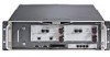
1 Overview Figure 1 shows the component locations for IP2255 appliances. Figure 1 Component Locations Front View Fan tray System status LEDs Network interface cards (4) SLOT 1 10Base-SR X2 A L 10Base-SR X2 A L SLOT 2 RESET CONSOLE AUX PCMCIA SLOT 3 10/100 BaseT 1 3 10/100 BaseT 2 4 1 3 2 4 SLOT 4 10/100/1000BaseT 5 7 6 8 5 7 6 8 SLOT 5 1 3 57 L A L A 2 4 68 1 3 57 L A L A 2 4 68 1 2 3 4 IP2255 00010 Console port Serial (AUX) port PC-card slots 10/100/1000 Ethernet management ports The flash memory in the internal compact-flash slot provides the primary application and operating system storage. The power supplies are located at the back of the IP2255 appliance, as shown in Figure 2. 22 Nokia IP2255 Security Platform Installation Guide
-
 1
1 -
2
-
3
-
4
-
5
-
6
-
7
-
8
-
9
-
10
-
11
-
12
-
13
-
14
-
15
-
16
-
 17
17 -
 18
18 -
 19
19 -
 20
20 -
 21
21 -
 22
22 -
 23
23 -
 24
24 -
 25
25 -
 26
26 -
 27
27 -
28
-
29
-
30
-
31
-
32
-
33
-
34
-
35
-
36
-
37
-
38
-
39
-
40
-
41
-
42
-
43
-
44
-
45
-
46
-
47
-
48
-
49
-
50
-
51
-
52
-
53
-
54
-
55
-
56
-
57
-
58
-
59
-
60
-
61
-
62
-
63
-
64
-
65
-
66
-
67
-
68
-
69
-
70
-
71
-
72
-
73
-
74
-
75
-
76
-
77
-
78
-
79
-
80
-
81
-
82
-
83
-
84
-
85
-
86
-
87
-
88
-
89
-
90
-
91
-
92
-
93
-
94
-
95
-
96
-
97
-
98
-
99
-
100
-
101
-
102
-
103
-
104
-
105
-
106
-
107
-
108
-
109
-
110
-
111
-
112
-
113
-
114
-
115
-
116
-
117
-
118
-
119
-
120
-
121
-
122
-
123
-
124
 |
 |

1
Overview
22
Nokia IP2255 Security Platform Installation Guide
Figure 1
shows the component locations for IP2255 appliances.
Figure 1
Component Locations Front View
The flash memory in the internal compact-flash slot provides the primary
application and operating system storage.
The power supplies are located at the back of the IP2255 appliance, as shown
in
Figure 2
.
00010
1
2
3
4
10/100/1000BaseT
IP2255
10Base-SR X2
10/100 BaseT
10/100 BaseT
10Base-SR X2
A
L
A
L
1
3
5
7
2
4
6
8
1
3
5
7
2
4
6
8
1
3
5
7
2
4
6
8
1
3
5
7
2
4
6
8
L
A
L
A
L
A
L
A
SLOT 3
SLOT 4
SLOT 1
SLOT 2
SLOT 5
CONSOLE
PCMCIA
RESET
Console port
Fan tray
System status LEDs
PC-card slots
10/100/1000 Ethernet
management ports
Serial (AUX) port
Network interface cards (4)