Panasonic 72 Service Manual - Page 44
Assembly of Display Unit
 |
UPC - 092281808376
View all Panasonic 72 manuals
Add to My Manuals
Save this manual to your list of manuals |
Page 44 highlights
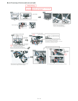
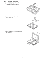
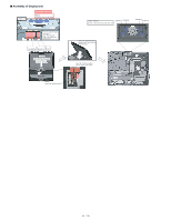
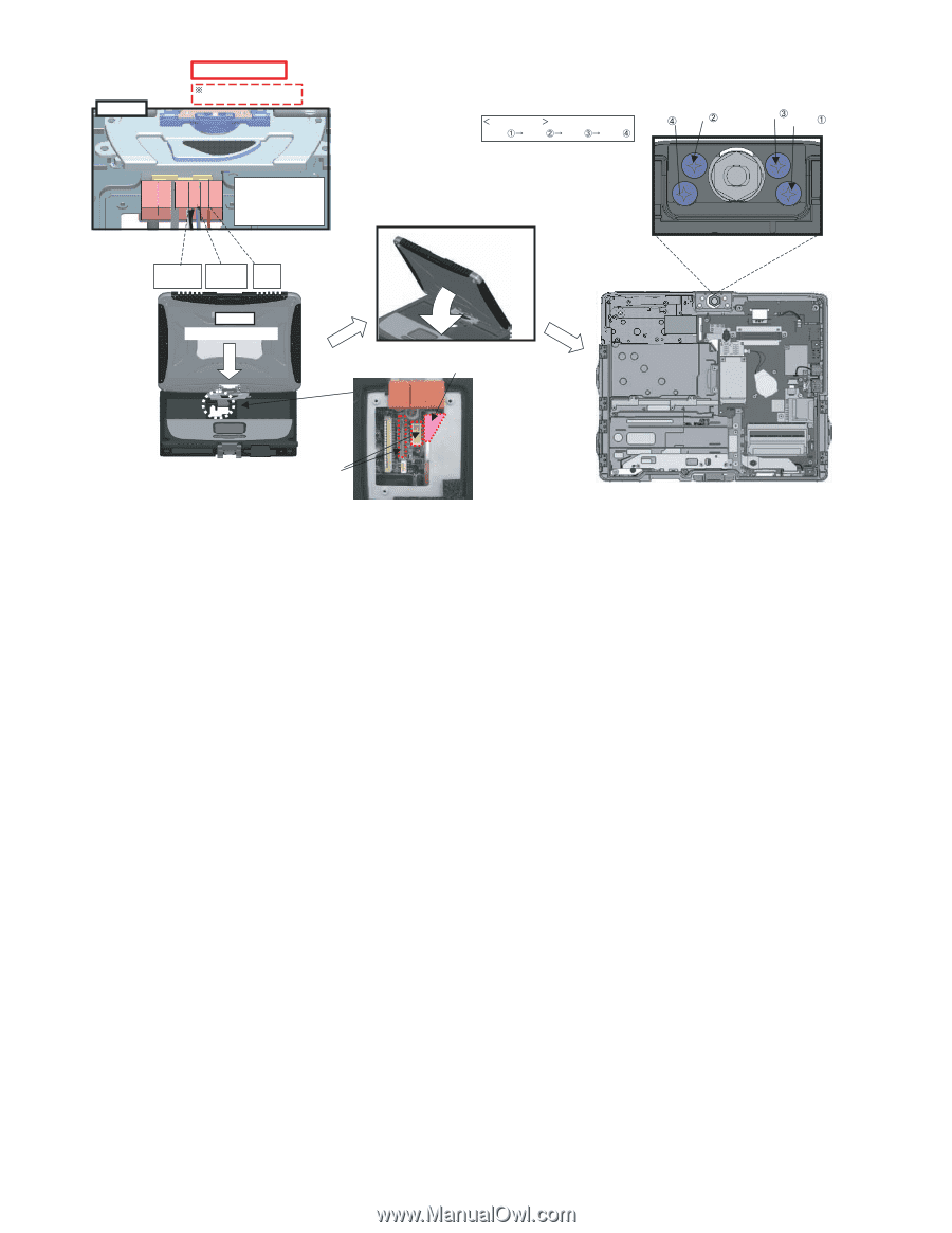
■ Assembly of Display Unit Details of "A" Safety Working Note Avoid any stress on the Cable. Pass the Cable through the groove. Note: Running over affects the waterproof performance.. Black/White Blue/Gray Brown LCD UNIT Set to the Top Case Assy A LCD Cable Insert Position Order of fixing Screw Screw Screw Screw Screw Screw Screw Screw Close the LCD hooking the Hinge on the Top Case, and then fold back. Insert all of antenna cables into the notch of the board.
-
 1
1 -
2
-
3
-
4
-
5
-
6
-
7
-
8
-
9
-
10
-
11
-
12
-
13
-
14
-
15
-
16
-
17
-
18
-
19
-
20
-
21
-
22
-
23
-
24
-
25
-
26
-
27
-
28
-
29
-
30
-
31
-
32
-
33
-
34
-
35
-
36
-
37
-
38
-
 39
39 -
 40
40 -
 41
41 -
 42
42 -
 43
43 -
 44
44 -
 45
45 -
 46
46 -
 47
47 -
 48
48 -
 49
49 -
50
-
51
-
52
-
53
-
54
-
55
-
56
-
57
-
58
-
59
-
60
-
61
-
62
-
63
-
64
-
65
-
66
-
67
-
68
-
69
-
70
-
71
-
72
-
73
-
74
-
75
-
76
-
77
-
78
-
79
-
80
-
81
-
82
-
83
-
84
-
85
-
86
-
87
-
88
-
89
-
90
 |
 |
■
Assembly of Display Unit
LCDUNIT
A
Note
AvoidanystressontheCable.
SafetyWorking
Detailsof"A"
Screw
Screw
Screw
Screw
Screw
Screw
Screw
Screw
Orderoffixing
ClosetheLCDhookingthe
HingeontheTopCase,and
thenfoldback.
Insertallofantennacables
intothenotchoftheboard.
LCDCableInsertPosition
SettotheTopCaseAssy
Black/White Blue/Gray Brown
PasstheCablethrough
thegroove.
Note:Runningover
affectsthewaterproof
performance..
44 / 90