Panasonic 72 Service Manual - Page 59
Assembling the DU Lid Unit, 2.15., Setting the Rear Cabinet
 |
UPC - 092281808376
View all Panasonic 72 manuals
Add to My Manuals
Save this manual to your list of manuals |
Page 59 highlights
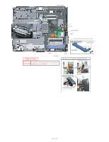
9.2.14. Assembling the DU Lid Unit 1. Fix the DU Lid Angle and the DU Lid using the 7 Screws. Screws : DXQT2+D25FNL DIMM Lid Angle DU Lid 9.2.15. Setting the Rear Cabinet 1. Fix the Rear Cabinet on the Computer using the 13 Screws. 2. Close the Lid Covers. Note: Tighten the Screws in the numbered order (No1 to No13). Screws : DRHM0061ZA :No.3 :No.11 :No.12 :No.2 :No.9 :No.7 :No.10 :No.5 :No.13 :No.1 :No.6 :No.8 :No.4
-
 1
1 -
2
-
3
-
4
-
5
-
6
-
7
-
8
-
9
-
10
-
11
-
12
-
13
-
14
-
15
-
16
-
17
-
18
-
19
-
20
-
21
-
22
-
23
-
24
-
25
-
26
-
27
-
28
-
29
-
30
-
31
-
32
-
33
-
34
-
35
-
36
-
37
-
38
-
39
-
40
-
41
-
42
-
43
-
44
-
45
-
46
-
47
-
48
-
49
-
50
-
51
-
52
-
53
-
 54
54 -
 55
55 -
 56
56 -
 57
57 -
 58
58 -
 59
59 -
 60
60 -
 61
61 -
 62
62 -
 63
63 -
 64
64 -
65
-
66
-
67
-
68
-
69
-
70
-
71
-
72
-
73
-
74
-
75
-
76
-
77
-
78
-
79
-
80
-
81
-
82
-
83
-
84
-
85
-
86
-
87
-
88
-
89
-
90
 |
 |
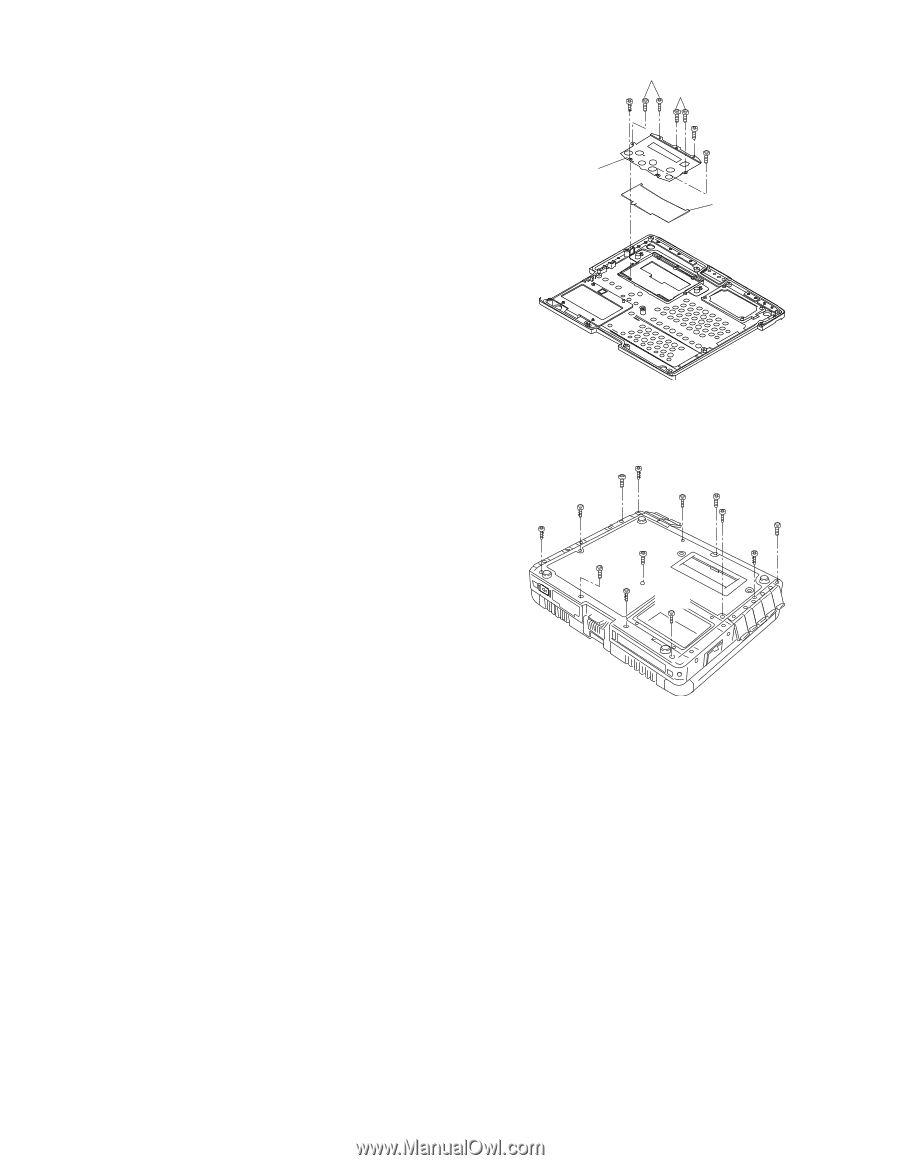
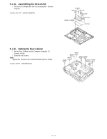
9.2.14.
Assembling the DU Lid Unit
1.FixtheDULidAngleandtheDULidusingthe7Screws.
<K14-9>
Screws<K14-9>:DXQT2+D25FNL
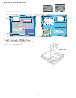
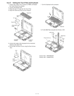
9.2.15.
Setting the Rear Cabinet
1.FixtheRearCabinetontheComputerusingthe13
Screws.<N10>
2.ClosetheLidCovers.
Note:
TightentheScrewsinthenumberedorder(No1toNo13).
Screws<N10>:DRHM0061ZA
<K14-9>
<K14-9>
DIMMLidAngle
DULid
<K14-9>
<K14-9>
<K14-9>
<N10>
:No.3
<N10>
:No.11
<N10>
:No.12
<N10>
:No.2
<N10>
:No.6
<N10>
:No.8
<N10>
:No.13
<N10>
:No.9
<N10>
:No.7
<N10>
:No.5
<N10>
:No.1
<N10>
:No.4
<N10>
:No.10
59 / 90