Panasonic 72 Service Manual - Page 51
Assembly of Main PCB
 |
UPC - 092281808376
View all Panasonic 72 manuals
Add to My Manuals
Save this manual to your list of manuals |
Page 51 highlights
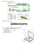
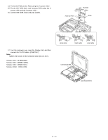
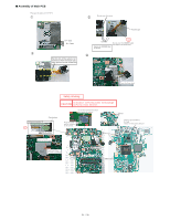
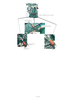
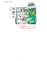
■ Assembly of Main PCB Process in the order of 1 2 3 4. Electric wire of the cabel is not sticked out from the black tape. Tape portion can be sticked out. Do not cover the screw Fold the tape Turn over Setting the MODEM label to the line S2 Do not cover the MODEM cable and Tape to the screw land Safety Working CAUTION S1:Insulation S2:Pinching Cables S3:Sharp Edge S4:Part No. Check S5:Others S1
-
 1
1 -
2
-
3
-
4
-
5
-
6
-
7
-
8
-
9
-
10
-
11
-
12
-
13
-
14
-
15
-
16
-
17
-
18
-
19
-
20
-
21
-
22
-
23
-
24
-
25
-
26
-
27
-
28
-
29
-
30
-
31
-
32
-
33
-
34
-
35
-
36
-
37
-
38
-
39
-
40
-
41
-
42
-
43
-
44
-
45
-
 46
46 -
 47
47 -
 48
48 -
 49
49 -
 50
50 -
 51
51 -
 52
52 -
 53
53 -
 54
54 -
 55
55 -
 56
56 -
57
-
58
-
59
-
60
-
61
-
62
-
63
-
64
-
65
-
66
-
67
-
68
-
69
-
70
-
71
-
72
-
73
-
74
-
75
-
76
-
77
-
78
-
79
-
80
-
81
-
82
-
83
-
84
-
85
-
86
-
87
-
88
-
89
-
90
 |
 |
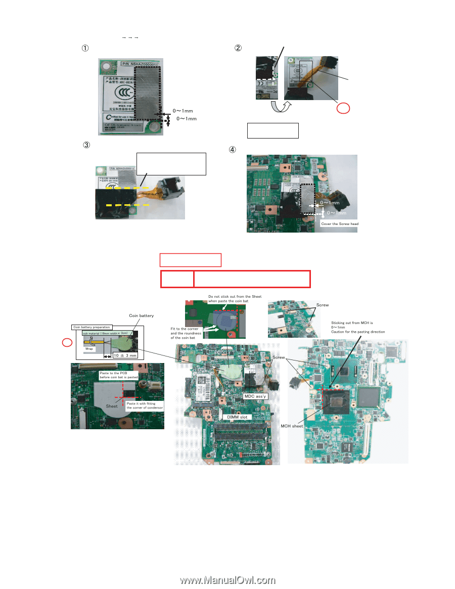
■
Assembly of Main PCB
Processintheorderof1 2 3 4.
S2
Donotcoverthescrew
Turnover
DonotcovertheMODEMcable
andTapetothescrewland
SettingtheMODEMlabel
totheline
Foldthetape
Electricwireofthecabelisnot
stickedoutfromtheblacktape.
Tapeportioncanbestickedout.
S1
S1:Insulation S2:Pinching Cables S3:Sharp Edge
S4:PartNo.CheckS5:Others
SafetyWorking
CAUTION
51 / 90