Panasonic 72 Service Manual - Page 54
CAUTION, SafetyWorking
 |
UPC - 092281808376
View all Panasonic 72 manuals
Add to My Manuals
Save this manual to your list of manuals |
Page 54 highlights
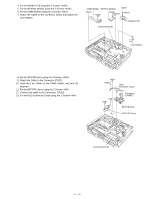
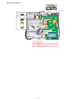
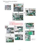
Thermal Rubber Screw HDD Connector Guide Screw A Screw SD PCB Ass'y Screw Screw Ensure that the knob is fit to SW when setting. DIMM HOLDER Ass'y RF SW Knob Insert the hook Safety Working Screw Insert the FPC CAUTION S1:Insulation S2:Pinching Cables S4:Part No. Check S5:Others S3:Sharp Edge Screw DIMM Holder Detail of portion A (assemble the LAN/MODEM HOLDER) LAN/MODEM HOLDER Figure from oblique view Put the claw under the MAIN PCB. S2 Put the cables into the hollow space of the HOLDER.
-
 1
1 -
2
-
3
-
4
-
5
-
6
-
7
-
8
-
9
-
10
-
11
-
12
-
13
-
14
-
15
-
16
-
17
-
18
-
19
-
20
-
21
-
22
-
23
-
24
-
25
-
26
-
27
-
28
-
29
-
30
-
31
-
32
-
33
-
34
-
35
-
36
-
37
-
38
-
39
-
40
-
41
-
42
-
43
-
44
-
45
-
46
-
47
-
48
-
 49
49 -
 50
50 -
 51
51 -
 52
52 -
 53
53 -
 54
54 -
 55
55 -
 56
56 -
 57
57 -
 58
58 -
 59
59 -
60
-
61
-
62
-
63
-
64
-
65
-
66
-
67
-
68
-
69
-
70
-
71
-
72
-
73
-
74
-
75
-
76
-
77
-
78
-
79
-
80
-
81
-
82
-
83
-
84
-
85
-
86
-
87
-
88
-
89
-
90
 |
 |

SD PCB Ass'y
DIMMHOLDERAss'y
EnsurethattheknobisfittoSWwhensetting.
InserttheFPC
Insertthehook
A
DetailofportionA(assembletheLAN/MODEMHOLDER)
LAN/MODEMHOLDER
Puttheclawunderthe
MAINPCB.
S2
CAUTION
S1:Insulation S2:Pinching Cables S3:Sharp Edge
S4:PartNo.CheckS5:Others
SafetyWorking
Figurefromobliqueview
Putthecablesintothehollow
spaceoftheHOLDER.
HDDConnectorGuide
Screw
Screw
Screw
Screw
Screw
Screw
ThermalRubber
DIMMHolder
RFSWKnob
Screw
54 / 90