Pioneer DV-C36 Owner's Manual - Page 17
Video Connections, System Control Connections - av cable
 |
View all Pioneer DV-C36 manuals
Add to My Manuals
Save this manual to your list of manuals |
Page 17 highlights
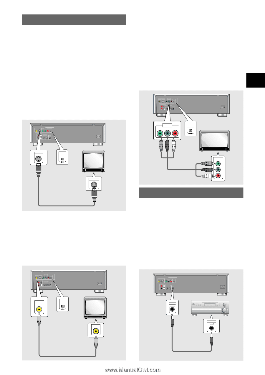
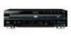
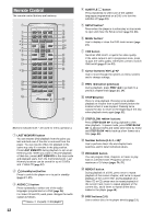
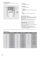
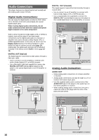
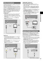
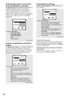
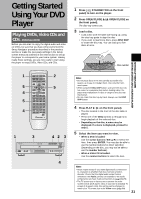
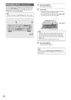
MAKING CONNECTIONS Video Connections This player features S-video, composite, and component video output possibilities. Check the manual supplied with your TV or monitor to determine the best possible connection for your system. In addition to making physical connections to your TV or monitor, it is also necessary to assign the TV screen size. You can use the [Setup Navigator] in the Setup screen General to set whether you are using a wide screen or standard size TV or monitor (page 19). Additionally, you can use the [TV Screen] setting in the Setup screen Video menu (page 30). S-VIDEO OUT • Make S-video connections to a TV or monitor with S- video input to produce a high quality video image. • Use an S-video cable (not supplied) to connect the S- VIDEO OUT jack on the player to S-video input on the TV or monitor. • When using this jack, be sure to set VIDEO OUT SELECT to the left position. VIDEO OUT S-VIDEO OUT COMPONENT VIDEO OUT Y PB PR VIDEO OUT SELECT AUDIO OUT R L 1 2 DIGITAL OUT OPT. CONTROL AC IN S-VIDEO OUT VIDEO OUT SELECT TV or monitor S-VIDEO IN VIDEO OUT • Make composite video connections to a standard TV or monitor with a video input jack. • Use the supplied video cable to connect the VIDEO OUT jack on the player to the video input on the TV or monitor. • Be sure to match the color of the plug with the color of the jack (yellow). • When using this jack, be sure to set VIDEO OUT SELECT to the left position. VIDEO OUT S-VIDEO OUT COMPONENT VIDEO OUT Y PB PR VIDEO OUT SELECT AUDIO OUT R L 1 2 DIGITAL OUT OPT. CONTROL AC IN VIDEO OUT VIDEO OUT SELECT TV or monitor COMPONENT VIDEO OUT (Interlace/Progressive-scan) • Make component video connections to a TV or monitor with component inputs to produce a higher quality video image. • Use a component video cable or 3 video cords (not supplied) to connect the COMPONENT VIDEO OUT jacks on the player to the component jacks on the monitor. • If connected to a progressive-scan compatible TV, set the [Component Video] menu to [Progressive] or [Auto Progressive](page 32). • When making component video connections, make sure to set the VIDEO OUT SELECT switch on the rear panel of the player to the right to assign component video output. VIDEO OUT S-VIDEO OUT COMPONENT VIDEO OUT Y PB PR VIDEO OUT SELECT AUDIO OUT R L 1 2 DIGITAL OUT OPT. CONTROL AC IN COMPONENT VIDEO OUT Y PB PR VIDEO OUT SELECT TV or monitor COMPONENT VIDEO IN Y PB PR System Control Connections Using a commercially available cord with a mini plug (3.5 mm dia. with no resistance) to connect this player's CONTROL IN jack to the CONTROL OUT jack of another PIONEER component bearing the Î mark, you can control the player as though it were a component in a system (system control). • If you connect for system control, you cannot operate the player directly. Point the remote control unit at the component (AV amplifier, etc.) connected to the CONTROL OUT jack to operate. • When controlling as a system, be sure to make a connection to the amplifier using an audio or video cord, even when using only digital components. • For details, refer to the operation manuals of the connected components. VIDEO OUT S-VIDEO OUT COMPONENT VIDEO OUT Y PB PR VIDEO OUT SELECT AUDIO OUT R L 1 2 DIGITAL OUT OPT. CONTROL AC IN CONTROL IN VIDEO IN CONTROL OUT Pioneer component with Î mark. 17
-
 1
1 -
2
-
3
-
4
-
5
-
6
-
7
-
8
-
9
-
10
-
11
-
 12
12 -
 13
13 -
 14
14 -
 15
15 -
 16
16 -
 17
17 -
 18
18 -
 19
19 -
 20
20 -
 21
21 -
 22
22 -
23
-
24
-
25
-
26
-
27
-
28
-
29
-
30
-
31
-
32
-
33
-
34
-
35
-
36
-
37
-
38
-
39
-
40
-
41
-
42
-
43
-
44
-
45
-
46
-
47
-
48
-
49
-
50
-
51
-
52
-
53
-
54
-
55
-
56
-
57
-
58
-
59
-
60
-
61
-
62
-
63
-
64
 |
 |