Pioneer PRO110FD Owner's Manual - Page 15
PRO-150FD, PRO-110FD - pro parts
 |
UPC - 012562864976
View all Pioneer PRO110FD manuals
Add to My Manuals
Save this manual to your list of manuals |
Page 15 highlights
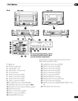
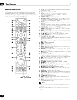
Part Names (Rear) PRO-150FD 04 PRO-110FD 4 5 4 5 4 5 4 5 1 20 21 22 2 3 45 14 4 5 15 16 17 23 6 8 10 11 12 13 18 19 24 7 9 25 *For exact terminal positions, refer to 27 26 the terminal position sheet located near the terminal compartment. The terminals on the rear panel are common to the PRO-150FD and PRO-110FD. 1 a button 2 Ethernet cable port 3 CableCARD™ slot 4 ANT/CABLE A IN terminal 5 AC IN terminal 6 INPUT 4 terminal (HDMI) 7 INPUT 5 terminal (HDMI) 8 INPUT 6 terminal (HDMI) 9 INPUT 7 terminal (HDMI) 10 PC INPUT terminal (ANALOG RGB) 11 CONTROL OUT terminal (supports SR+) 12 RS-232C terminal (used for factory setup) 13 ANT B IN terminal 14 INPUT 1 terminal (S-VIDEO) 15 INPUT 1 terminal (VIDEO) 16 SUBWOOFER terminal 17 AUDIO OUT terminals (AUDIO) 18 INPUT 1 terminals (AUDIO) 19 INPUT 2 terminals (AUDIO) 20 INPUT 4 terminals (AUDIO) 21 INPUT 5 terminals (AUDIO) 22 INPUT 2 terminal (VIDEO) 23 IR REPEATER OUT terminal 24 DIGITAL OUT terminal (OPTICAL) 25 PC INPUT terminal (AUDIO) 26 INPUT 2 terminals (COMPONENT VIDEO: Y, PB, PR) 27 SPEAKERS (R/L) terminals 15 En
-
 1
1 -
2
-
3
-
4
-
5
-
6
-
7
-
8
-
9
-
 10
10 -
 11
11 -
 12
12 -
 13
13 -
 14
14 -
 15
15 -
 16
16 -
 17
17 -
 18
18 -
 19
19 -
 20
20 -
21
-
22
-
23
-
24
-
25
-
26
-
27
-
28
-
29
-
30
-
31
-
32
-
33
-
34
-
35
-
36
-
37
-
38
-
39
-
40
-
41
-
42
-
43
-
44
-
45
-
46
-
47
-
48
-
49
-
50
-
51
-
52
-
53
-
54
-
55
-
56
-
57
-
58
-
59
-
60
-
61
-
62
-
63
-
64
-
65
-
66
-
67
-
68
-
69
-
70
-
71
-
72
-
73
-
74
-
75
-
76
-
77
-
78
-
79
-
80
-
81
-
82
-
83
-
84
-
85
-
86
-
87
-
88
-
89
-
90
-
91
-
92
-
93
-
94
-
95
-
96
-
97
-
98
-
99
-
100
-
101
-
102
-
103
-
104
-
105
-
106
-
107
-
108
-
109
-
110
-
111
-
112
-
113
-
114
-
115
-
116
-
117
-
118
-
119
-
120
-
121
-
122
-
123
-
124
-
125
-
126
 |
 |
