Samsung SCX 6322DN Service Manual - Page 19
System Overview - paper jam sensor
 |
UPC - 635753620658
View all Samsung SCX 6322DN manuals
Add to My Manuals
Save this manual to your list of manuals |
Page 19 highlights
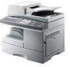
33. System Overview 3.1 System Construction System Overview 3.1.1 Printer Printer consists of the Engine parts and F/W, and engine parts consist of the mechanical parts comprising Frame, Feeding, Developing, Driving, Transferring, Fusing, Cabinet and H/W comprising the main control board, power board, operation panel, PC Interface. The main controller consists of ASIC (CHORUSm) parts, Memory parts, Engine Interface parts and it functions as Bus Control, I/O Handling, drivers & PC Interface by CPU. The Engine Board and the Controller Board are in one united board, and it consists of CPU part and print part in functional aspect. The CPU is functioned as the bus control, I/O handling, drivers, and PC interface. The main board sends the Current Image, Video data to the LSU and manages the conduct of Electro photography for printing. It consists of the circuits of the motor (paper feed, pass) driving, clutch driving, pre-transfer lamp driving, current driving, and fan driving. The signals from the paper feed jam sensor and paper empty sensor are directly inputted to the main board. 3.1.2 Scanner Pictorial signal input part : output signal of CCD passes through Bypass Cap change to ADC at HT82V26A, and defined signal between HT82V26A and CHORUSm processes the Image signal. When AFE accept each pixel, CDS(Correlated Double Sampling ) technique which samples arm-level twice is used on each pixel by using CHORUSm IP signal. Pictorial image processing part : read CCD Pixel data in terms of 600dpi Line and process Error Diffusion Algorithm on Text mode and Photo mode, and then store Data at Scan Buffer on PC Scan mode without algorithm. On every mode Shading Correction and Gamma Correction are executed ahead, then processing is executed later. Samsung Electronics Service Manual 3-1
-
 1
1 -
2
-
3
-
4
-
5
-
6
-
7
-
8
-
9
-
10
-
11
-
12
-
13
-
 14
14 -
 15
15 -
 16
16 -
 17
17 -
 18
18 -
 19
19 -
 20
20 -
 21
21 -
 22
22 -
 23
23 -
 24
24 -
25
-
26
-
27
-
28
-
29
-
30
-
31
-
32
-
33
-
34
-
35
-
36
-
37
-
38
-
39
-
40
-
41
-
42
-
43
-
44
-
45
-
46
-
47
-
48
-
49
-
50
-
51
-
52
-
53
-
54
-
55
-
56
-
57
-
58
-
59
-
60
-
61
-
62
-
63
-
64
-
65
-
66
-
67
-
68
-
69
-
70
-
71
-
72
-
73
-
74
-
75
-
76
-
77
-
78
-
79
-
80
-
81
-
82
-
83
-
84
-
85
-
86
-
87
-
88
-
89
-
90
-
91
-
92
-
93
-
94
-
95
-
96
-
97
-
98
-
99
-
100
-
101
-
102
-
103
-
104
-
105
-
106
-
107
-
108
-
109
-
110
-
111
-
112
-
113
-
114
-
115
-
116
-
117
-
118
-
119
-
120
-
121
-
122
-
123
-
124
-
125
-
126
-
127
-
128
-
129
-
130
-
131
-
132
-
133
-
134
-
135
-
136
-
137
-
138
-
139
-
140
-
141
-
142
-
143
-
144
-
145
-
146
-
147
-
148
-
149
-
150
-
151
-
152
-
153
-
154
-
155
-
156
-
157
-
158
-
159
-
160
-
161
-
162
-
163
-
164
-
165
-
166
-
167
-
168
-
169
-
170
-
171
-
172
-
173
-
174
-
175
-
176
-
177
-
178
-
179
-
180
-
181
-
182
-
183
-
184
-
185
 |
 |