Samsung SCX 6322DN Service Manual - Page 51
Abnormal Image Printing and Defective Roller
 |
UPC - 635753620658
View all Samsung SCX 6322DN manuals
Add to My Manuals
Save this manual to your list of manuals |
Page 51 highlights
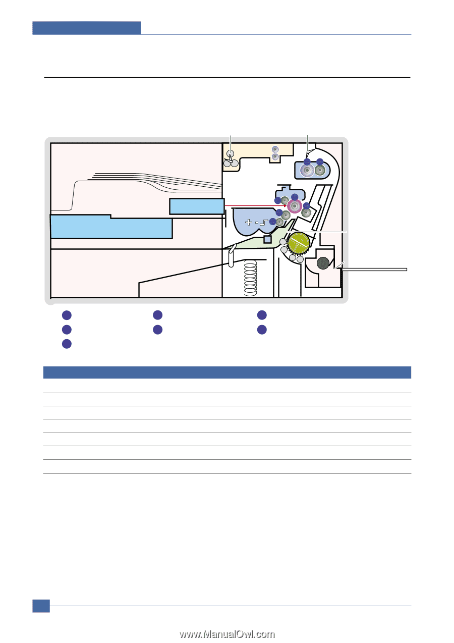
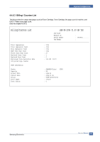
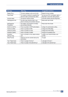
Alignment & Adjustments 4.6 Abnormal Image Printing and Defective Roller If a mark or other printing defect occurs at regular intervals down the page it may be caused by a damaged or contaminated roller. Measure the repetition interval and refer to the table below to identify the roller concerned. Main Board+Engine Board SMPS EBXINITFUSELNLSSOERNSOR EXIT SENSOR EXIT UNIT OPCFUSNEITR 67 LIU OPC UNIT 2 TONER UNIT 4 3 1 5 OPC DRUM TR FTL EMPTY SEN PICKUP ROLL FEEDER FEED SENSOR EMPTY SENSOR(MPF) MPF 1 OPC Drum 2 Charge Roller 3 Supply Roller 4 Developing Roller 5 Transfer Roller 6 Heat Roller 7 Pressure Roller No Roller Abnormal image period Kind of abnormal image 1 OPC Drum 94.30mm White spot, Block spot 2 Charge Roller 38.30mm Black spot 3 Supply Roller 43.80mm Horizontal density band 4 Develop Roller 54.30mm Horizontal density band 5 Transfer Roller 56.60mm Black side contamination/transfer fault 6 Heat Roller 83.60mm Black spot and fuser ghost 7 Pressure Roller 91.00mm Black side contamination 4-24 Service Manual Samsung Electronics
-
 1
1 -
2
-
3
-
4
-
5
-
6
-
7
-
8
-
9
-
10
-
11
-
12
-
13
-
14
-
15
-
16
-
17
-
18
-
19
-
20
-
21
-
22
-
23
-
24
-
25
-
26
-
27
-
28
-
29
-
30
-
31
-
32
-
33
-
34
-
35
-
36
-
37
-
38
-
39
-
40
-
41
-
42
-
43
-
44
-
45
-
 46
46 -
 47
47 -
 48
48 -
 49
49 -
 50
50 -
 51
51 -
 52
52 -
 53
53 -
 54
54 -
 55
55 -
 56
56 -
57
-
58
-
59
-
60
-
61
-
62
-
63
-
64
-
65
-
66
-
67
-
68
-
69
-
70
-
71
-
72
-
73
-
74
-
75
-
76
-
77
-
78
-
79
-
80
-
81
-
82
-
83
-
84
-
85
-
86
-
87
-
88
-
89
-
90
-
91
-
92
-
93
-
94
-
95
-
96
-
97
-
98
-
99
-
100
-
101
-
102
-
103
-
104
-
105
-
106
-
107
-
108
-
109
-
110
-
111
-
112
-
113
-
114
-
115
-
116
-
117
-
118
-
119
-
120
-
121
-
122
-
123
-
124
-
125
-
126
-
127
-
128
-
129
-
130
-
131
-
132
-
133
-
134
-
135
-
136
-
137
-
138
-
139
-
140
-
141
-
142
-
143
-
144
-
145
-
146
-
147
-
148
-
149
-
150
-
151
-
152
-
153
-
154
-
155
-
156
-
157
-
158
-
159
-
160
-
161
-
162
-
163
-
164
-
165
-
166
-
167
-
168
-
169
-
170
-
171
-
172
-
173
-
174
-
175
-
176
-
177
-
178
-
179
-
180
-
181
-
182
-
183
-
184
-
185
 |
 |