Sanyo PDG-DHT8000L Owners Manual - Page 11
Terminals and Connectors, SERIAL PORT IN TERMINAL - manual
 |
View all Sanyo PDG-DHT8000L manuals
Add to My Manuals
Save this manual to your list of manuals |
Page 11 highlights
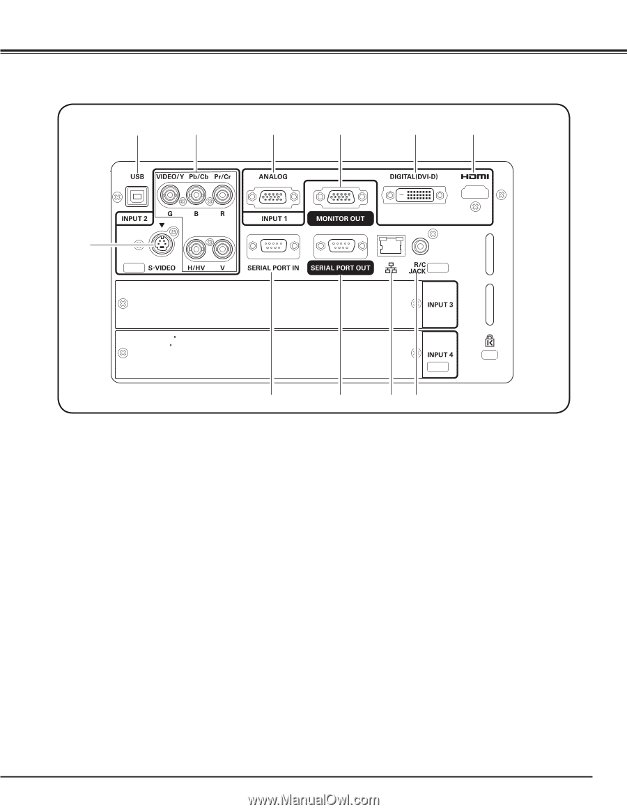
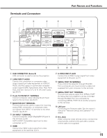
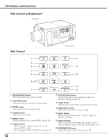
Terminals and Connectors q w e r Part Names and Functions t y u i o !0 !1 q USB CONNECTOR (Series B) USB connector is used to service the projector. w 5 BNC INPUT JACKS Connect the component or composite video output signal from video equipment to VIDEO/Y, Pb/Cb, and Pr/Cr jacks or connect the computer output signal (5 BNC Type [Green, Blue, Red, Horiz. Sync, and Vert. Sync.]) to G, B, R, H/V, and V jacks. (pp.20-21) e D-sub 15-PIN INPUT TERMINAL Connect computer output (Analog D-sub 15-pin type) to this terminal. (pp.20-21) r MONITOR OUT TERMINAL This terminal can be used to output the incoming analog RGB, component, or composite video out signals from INPUT 1-2 terminal to the other monitor. (pp.20-21) t DVI INPUT TERMINAL Connect computer output (Digital/DVI-D type) to this terminal. (p.20) HDTV (HDCP Compatible) signal can be also connected. (p.21) y HDMI Connect the HDMI output signal from video equipment to this terminal. (p.21) u S-VIDEO INPUT JACK Connect the S-VIDEO output signal from video equipment to this jack. (p.21) i SERIAL PORT IN TERMINAL If you control the projector through RS-232C from a computer, you must connect a cable (not supplied) from your computer to this terminal. o SERIAL PORT OUT TERMINAL This terminal outputs signal from SERIAL PORT IN. More than two projectors can be controlled through RS-232C from one computer by connecting SERIAL PORT IN of another projector to this terminal. !0 LAN port Connecting the Ethernet cable. See the owner's manual of "Network Set-up and Operation" for details. !1 R/C JACK When using the wired remote control, connect the wired remote control to this jack with a remote control cable (not supplied). 11
-
 1
1 -
2
-
3
-
4
-
5
-
 6
6 -
 7
7 -
 8
8 -
 9
9 -
 10
10 -
 11
11 -
 12
12 -
 13
13 -
 14
14 -
 15
15 -
 16
16 -
17
-
18
-
19
-
20
-
21
-
22
-
23
-
24
-
25
-
26
-
27
-
28
-
29
-
30
-
31
-
32
-
33
-
34
-
35
-
36
-
37
-
38
-
39
-
40
-
41
-
42
-
43
-
44
-
45
-
46
-
47
-
48
-
49
-
50
-
51
-
52
-
53
-
54
-
55
-
56
-
57
-
58
-
59
-
60
-
61
-
62
-
63
-
64
-
65
-
66
-
67
-
68
-
69
-
70
-
71
-
72
-
73
-
74
-
75
-
76
-
77
-
78
-
79
-
80
-
81
-
82
-
83
-
84
-
85
-
86
-
87
-
88
-
89
-
90
-
91
-
92
-
93
-
94
 |
 |