Sony KE-42TS2U Operating Instructions - Page 19
Connecting an RGB Equipment, US
 |
View all Sony KE-42TS2U manuals
Add to My Manuals
Save this manual to your list of manuals |
Page 19 highlights
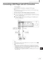
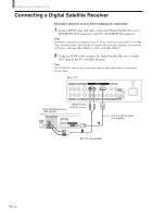
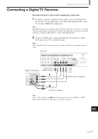
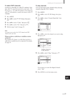
Connecting an RGB Equipment Installing and Connecting the TV Disconnect all power sources before making any connections. 1 Using an RGB cable, connect the RGB equipment's video/synchronized signal output terminal to the Y/G, PB/B, PR/R, HD, and VD jacks on the TV. Use the VIDEO IN 4 connections. 2 Using an AUDIO cable, connect the RGB equipment's AUDIO OUT jacks to the TV's AUDIO IN jacks. Be sure to use the same row of inputs that you used for the video connection. Rear of TV VIDEO IN 1 R AUDIO L VIDEO S VIDEO VIDEO IN 2 VIDEO IN 3 R AUDIO L DVI-HDTV AUDIO OUT R L R AUDIO L Y/G PB/B PR/R HD CONTROL S IN VD OUT VIDEO IN 4 SUB WOOFER RGB equipment VHF/UHF AC IN Note Set "Video 4 Mode" to "RGB" in the (Initial Setup) menu (see page 32). US (US) 19
-
 1
1 -
2
-
3
-
4
-
5
-
6
-
7
-
8
-
9
-
10
-
11
-
12
-
13
-
 14
14 -
 15
15 -
 16
16 -
 17
17 -
 18
18 -
 19
19 -
 20
20 -
 21
21 -
 22
22 -
 23
23 -
 24
24 -
25
-
26
-
27
-
28
-
29
-
30
-
31
-
32
-
33
-
34
-
35
-
36
-
37
-
38
-
39
-
40
-
41
-
42
-
43
-
44
-
45
-
46
-
47
-
48
-
49
-
50
-
51
-
52
-
53
-
54
-
55
-
56
-
57
-
58
-
59
-
60
-
61
-
62
-
63
-
64
-
65
-
66
-
67
-
68
-
69
-
70
-
71
-
72
-
73
-
74
-
75
-
76
-
77
-
78
-
79
-
80
-
81
-
82
-
83
-
84
-
85
-
86
-
87
-
88
-
89
-
90
-
91
-
92
-
93
-
94
-
95
-
96
-
97
-
98
-
99
-
100
-
101
-
102
-
103
-
104
-
105
-
106
-
107
-
108
-
109
-
110
-
111
-
112
-
113
-
114
-
115
-
116
-
117
-
118
-
119
-
120
-
121
-
122
-
123
-
124
-
125
-
126
-
127
-
128
-
129
-
130
-
131
-
132
-
133
-
134
-
135
-
136
-
137
-
138
-
139
-
140
-
141
-
142
-
143
-
144
-
145
-
146
-
147
-
148
-
149
-
150
-
151
-
152
-
153
-
154
-
155
-
156
-
157
-
158
-
159
-
160
-
161
-
162
-
163
-
164
-
165
-
166
-
167
-
168
-
169
-
170
-
171
-
172
-
173
-
174
-
175
-
176
-
177
-
178
-
179
-
180
-
181
-
182
-
183
-
184
-
185
-
186
-
187
-
188
 |
 |
