Toshiba Portege R500 User Manual - Page 34
Front with the display open, Memory module slot, Battery release latch, Battery lock - screen replacement
 |
View all Toshiba Portege R500 manuals
Add to My Manuals
Save this manual to your list of manuals |
Page 34 highlights
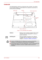
The Grand Tour Memory module slot The memory module slot allows for the installation, replacement and removal of additional memory module. Refer to the Additional memory module section in Chapter 3, Hardware, Utilities and Options. Battery release latch Slide and hold this latch into its 'Unlock' position in order to release the battery pack ready for removal. For more detailed information on removing the battery pack please refer to Chapter 6, Power and Power-Up Modes. Battery lock Slide the battery lock to release the battery pack for removal. Front with the display open This section shows the computer with the display panel open. In order to open the display, lift the display panel up and position it at a comfortable viewing angle for you. Display screen Display hinge LCD Sensor switch (Not shown) Display hinge TOSHIBA Assist button Back light On/Off button Fingerprint Sensor Speaker Power button Keyboard Microphone Touch Pad Touch Pad control buttons Figure 2-6 The front of the computer with the display panel open User's Manual 2-7
-
 1
1 -
2
-
3
-
4
-
5
-
6
-
7
-
8
-
9
-
10
-
11
-
12
-
13
-
14
-
15
-
16
-
17
-
18
-
19
-
20
-
21
-
22
-
23
-
24
-
25
-
26
-
27
-
28
-
 29
29 -
 30
30 -
 31
31 -
 32
32 -
 33
33 -
 34
34 -
 35
35 -
 36
36 -
 37
37 -
 38
38 -
 39
39 -
40
-
41
-
42
-
43
-
44
-
45
-
46
-
47
-
48
-
49
-
50
-
51
-
52
-
53
-
54
-
55
-
56
-
57
-
58
-
59
-
60
-
61
-
62
-
63
-
64
-
65
-
66
-
67
-
68
-
69
-
70
-
71
-
72
-
73
-
74
-
75
-
76
-
77
-
78
-
79
-
80
-
81
-
82
-
83
-
84
-
85
-
86
-
87
-
88
-
89
-
90
-
91
-
92
-
93
-
94
-
95
-
96
-
97
-
98
-
99
-
100
-
101
-
102
-
103
-
104
-
105
-
106
-
107
-
108
-
109
-
110
-
111
-
112
-
113
-
114
-
115
-
116
-
117
-
118
-
119
-
120
-
121
-
122
-
123
-
124
-
125
-
126
-
127
-
128
-
129
-
130
-
131
-
132
-
133
-
134
-
135
-
136
-
137
-
138
-
139
-
140
-
141
-
142
-
143
-
144
-
145
-
146
-
147
-
148
-
149
-
150
-
151
-
152
-
153
-
154
-
155
-
156
-
157
-
158
-
159
-
160
-
161
-
162
-
163
-
164
-
165
-
166
-
167
-
168
-
169
-
170
-
171
-
172
-
173
-
174
-
175
-
176
-
177
-
178
-
179
-
180
-
181
-
182
-
183
-
184
-
185
-
186
-
187
-
188
-
189
-
190
-
191
-
192
-
193
-
194
-
195
-
196
-
197
-
198
 |
 |
