Yamaha CVP-203 Owner's Manual - Page 155
CVP-203: Keyboard Stand Assembly
 |
View all Yamaha CVP-203 manuals
Add to My Manuals
Save this manual to your list of manuals |
Page 155 highlights
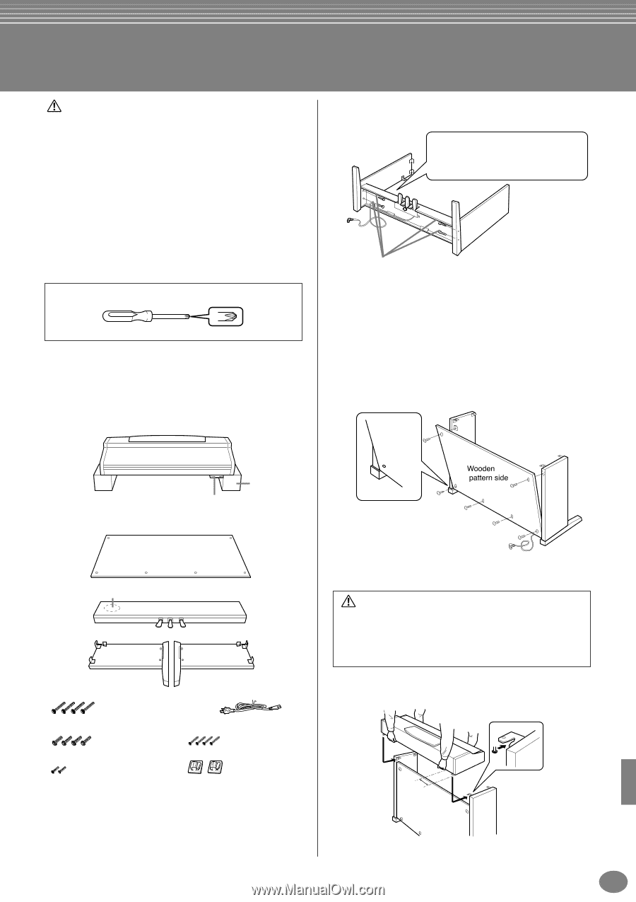
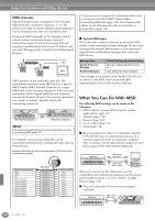
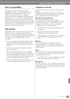
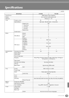
CVP-203: Keyboard Stand Assembly CAUTION I Be careful not to confuse parts, and be sure to install all parts in the correct direction. Please assemble in accordance with the sequence given below. I Assembly should be carried out by at least two persons. I Be sure to use the correct screw size, as indicated below. Use of incorrect screws can cause damage. I Be sure to tighten up all screws upon completing assembly of each unit. I To disassemble, reverse the assembly sequence given below. Have a Phillips-head (+) screwdriver ready. 1 Open the package, take out the pedal box, take out the styrofoam pads, and place the main unit on top of the pads. Position the pads so that they will protect the headphone jack and the connector panel located underneath the front left corner, and the floppy disk drive located underneath the front right corner. Main unit 2 Attach the side panels to the pedal box. Side panel (left) 1 Untie and straighten out the bundled cord attached to the bottom of the pedal box. Don't discard the vinyl tie, you'll need it later in step 6. Side panel (right) 2 Use the four 6x25 mm long screws to attach the pedal box. First attach one side panel, then attach the other side panel. 3 Attach the rear panel. 1 Place the bottom edges of the rear panel on the feet's protruding edges, with the panel slightly angled as shown in the illustration. The wooden pattern side of the panel should be facing outside. Then, align the top part of the panel with the side panels. 2 Secure the top of the rear panel to the side panel brackets using two 4x12 mm thin screws. 3 Secure the bottom of the rear panel to the pedal box using four 4x20 mm tapping screws. Floppy disk drive Styrofoam pads Remove the parts shown below from the box. Rear panel Pedal box Bundled pedal cord inside Side panel (left) Side panel (right) Assembly Parts 6 x 25 mm long screws x4 6 x 16 mm short screws x4 4 x 12 mm thin screws x2 AC power cord 4 x 20 mm tapping screws x4 Cord holders x2 4 Mount the main unit. CAUTION • Fingers can become pinched between the main unit and the rear or side panels, be extra careful so as not to drop the main unit. • Do not hold the keyboard in any position other than the position shown in the illustration. Be sure to place your hands at least 10 cm from either end of the main unit when positioning it. At least 10 cm CVP-205/203 155
-
 1
1 -
2
-
3
-
4
-
5
-
6
-
7
-
8
-
9
-
10
-
11
-
12
-
13
-
14
-
15
-
16
-
17
-
18
-
19
-
20
-
21
-
22
-
23
-
24
-
25
-
26
-
27
-
28
-
29
-
30
-
31
-
32
-
33
-
34
-
35
-
36
-
37
-
38
-
39
-
40
-
41
-
42
-
43
-
44
-
45
-
46
-
47
-
48
-
49
-
50
-
51
-
52
-
53
-
54
-
55
-
56
-
57
-
58
-
59
-
60
-
61
-
62
-
63
-
64
-
65
-
66
-
67
-
68
-
69
-
70
-
71
-
72
-
73
-
74
-
75
-
76
-
77
-
78
-
79
-
80
-
81
-
82
-
83
-
84
-
85
-
86
-
87
-
88
-
89
-
90
-
91
-
92
-
93
-
94
-
95
-
96
-
97
-
98
-
99
-
100
-
101
-
102
-
103
-
104
-
105
-
106
-
107
-
108
-
109
-
110
-
111
-
112
-
113
-
114
-
115
-
116
-
117
-
118
-
119
-
120
-
121
-
122
-
123
-
124
-
125
-
126
-
127
-
128
-
129
-
130
-
131
-
132
-
133
-
134
-
135
-
136
-
137
-
138
-
139
-
140
-
141
-
142
-
143
-
144
-
145
-
146
-
147
-
148
-
149
-
 150
150 -
 151
151 -
 152
152 -
 153
153 -
 154
154 -
 155
155 -
 156
156 -
 157
157 -
 158
158 -
 159
159 -
 160
160 -
161
-
162
-
163
-
164
-
165
-
166
-
167
-
168
-
169
-
170
 |
 |