2014 Ducati Hypermotard Hyperstrada Owners Manual - Page 227
2014 Ducati Hypermotard Hyperstrada Manual

Page 227 highlights
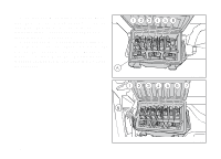
Injection /electric system diagram key 1) 2) 3) 4) 5) 6) 7) 8) 9) 10) 11) 12) 13) 14) 15) 16) 17) 18) 19) 20) 21) 22) 23) 24) Right-hand switch Ignition system (key-operated switch) Main relay Regulator Generator Navigator Front fuse box Starter motor Fused solenoid Battery Wiring ground Data Acquisition/Diagnosis Rear fuse box ABS control unit ABS Diagnosis Front speed sensor Rear speed sensor Right fan Left fan Rear light Rear right turn indicator Rear wiring loom Rear left turn indicator Exhaust valve starter motor 25) 26) 27) 28) 29) 30) 31) 32) 33) 34) 35) 36) 37) 38) 39) 40) 41) 42) 43) 44) 45) 46) 47) 48) Vehicle control unit (BBS) Anti-theft alarm Oil pressure switch Gear sensor Side stand switch Clutch switch Timing/rpm sensor Vertical MAP sensor Horizontal MAP sensor Engine temperature Vertical lambda sensor Horizontal lambda sensor Throttle twistgrip position sensor (APS) Ride-by-wire / potentiometer motor (TPS/ETV) horizontal Ride-by-wire / potentiometer motor (TPS/ETV) vertical Horizontal coil Vertical coil Main horizontal injector Main vertical injector Secondary air actuator Fuel pump Fuel pump relay Control unit - body connector Control unit - engine connector 225
-
 1
1 -
2
-
3
-
4
-
5
-
6
-
7
-
8
-
9
-
10
-
11
-
12
-
13
-
14
-
15
-
16
-
17
-
18
-
19
-
20
-
21
-
22
-
23
-
24
-
25
-
26
-
27
-
28
-
29
-
30
-
31
-
32
-
33
-
34
-
35
-
36
-
37
-
38
-
39
-
40
-
41
-
42
-
43
-
44
-
45
-
46
-
47
-
48
-
49
-
50
-
51
-
52
-
53
-
54
-
55
-
56
-
57
-
58
-
59
-
60
-
61
-
62
-
63
-
64
-
65
-
66
-
67
-
68
-
69
-
70
-
71
-
72
-
73
-
74
-
75
-
76
-
77
-
78
-
79
-
80
-
81
-
82
-
83
-
84
-
85
-
86
-
87
-
88
-
89
-
90
-
91
-
92
-
93
-
94
-
95
-
96
-
97
-
98
-
99
-
100
-
101
-
102
-
103
-
104
-
105
-
106
-
107
-
108
-
109
-
110
-
111
-
112
-
113
-
114
-
115
-
116
-
117
-
118
-
119
-
120
-
121
-
122
-
123
-
124
-
125
-
126
-
127
-
128
-
129
-
130
-
131
-
132
-
133
-
134
-
135
-
136
-
137
-
138
-
139
-
140
-
141
-
142
-
143
-
144
-
145
-
146
-
147
-
148
-
149
-
150
-
151
-
152
-
153
-
154
-
155
-
156
-
157
-
158
-
159
-
160
-
161
-
162
-
163
-
164
-
165
-
166
-
167
-
168
-
169
-
170
-
171
-
172
-
173
-
174
-
175
-
176
-
177
-
178
-
179
-
180
-
181
-
182
-
183
-
184
-
185
-
186
-
187
-
188
-
189
-
190
-
191
-
192
-
193
-
194
-
195
-
196
-
197
-
198
-
199
-
200
-
201
-
202
-
203
-
204
-
205
-
206
-
207
-
208
-
209
-
210
-
211
-
212
-
213
-
214
-
215
-
216
-
217
-
218
-
219
-
220
-
221
-
 222
222 -
 223
223 -
 224
224 -
 225
225 -
 226
226 -
 227
227 -
 228
228 -
 229
229 -
 230
230 -
 231
231 -
 232
232
 |
 |
