2014 Ducati Hypermotard Hyperstrada Owners Manual - Page 228
2014 Ducati Hypermotard Hyperstrada Manual

Page 228 highlights
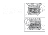
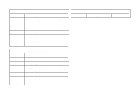
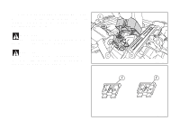
49) 50) 51) 52) 53) 54) 55) 56) 57) 58) 59) 60) 61) 62) Left-hand switch Front left turn indicator Horn Air temperature sensor Heated handgrips Instrument panel Rear stop Front stop Front right turn indicator Headlight Serial line Immobilizer Rider power outlet Passenger power outlet Bn Brown O Orange P Pink Note The electric system wiring diagram is at the end of this manual. Wire color coding B Blue W White V Violet Bk Black Y Yellow R Red Lb Light blue Gr Gray G Green 226
-
 1
1 -
2
-
3
-
4
-
5
-
6
-
7
-
8
-
9
-
10
-
11
-
12
-
13
-
14
-
15
-
16
-
17
-
18
-
19
-
20
-
21
-
22
-
23
-
24
-
25
-
26
-
27
-
28
-
29
-
30
-
31
-
32
-
33
-
34
-
35
-
36
-
37
-
38
-
39
-
40
-
41
-
42
-
43
-
44
-
45
-
46
-
47
-
48
-
49
-
50
-
51
-
52
-
53
-
54
-
55
-
56
-
57
-
58
-
59
-
60
-
61
-
62
-
63
-
64
-
65
-
66
-
67
-
68
-
69
-
70
-
71
-
72
-
73
-
74
-
75
-
76
-
77
-
78
-
79
-
80
-
81
-
82
-
83
-
84
-
85
-
86
-
87
-
88
-
89
-
90
-
91
-
92
-
93
-
94
-
95
-
96
-
97
-
98
-
99
-
100
-
101
-
102
-
103
-
104
-
105
-
106
-
107
-
108
-
109
-
110
-
111
-
112
-
113
-
114
-
115
-
116
-
117
-
118
-
119
-
120
-
121
-
122
-
123
-
124
-
125
-
126
-
127
-
128
-
129
-
130
-
131
-
132
-
133
-
134
-
135
-
136
-
137
-
138
-
139
-
140
-
141
-
142
-
143
-
144
-
145
-
146
-
147
-
148
-
149
-
150
-
151
-
152
-
153
-
154
-
155
-
156
-
157
-
158
-
159
-
160
-
161
-
162
-
163
-
164
-
165
-
166
-
167
-
168
-
169
-
170
-
171
-
172
-
173
-
174
-
175
-
176
-
177
-
178
-
179
-
180
-
181
-
182
-
183
-
184
-
185
-
186
-
187
-
188
-
189
-
190
-
191
-
192
-
193
-
194
-
195
-
196
-
197
-
198
-
199
-
200
-
201
-
202
-
203
-
204
-
205
-
206
-
207
-
208
-
209
-
210
-
211
-
212
-
213
-
214
-
215
-
216
-
217
-
218
-
219
-
220
-
221
-
222
-
 223
223 -
 224
224 -
 225
225 -
 226
226 -
 227
227 -
 228
228 -
 229
229 -
 230
230 -
 231
231 -
 232
232
 |
 |
49)
Left-hand switch
50)
Front left turn indicator
51)
Horn
52)
Air temperature sensor
53)
Heated handgrips
54)
Instrument panel
55)
Rear stop
56)
Front stop
57)
Front right turn indicator
58)
Headlight
59)
Serial line
60)
Immobilizer
61)
Rider power outlet
62)
Passenger power outlet
Wire color coding
B Blue
W White
V Violet
Bk Black
Y Yellow
R Red
Lb Light blue
Gr Gray
G Green
Bn Brown
O Orange
P Pink
Note
The electric system wiring diagram is at the end
of this manual.
226